Hi all,
I'm planning on building the current-mode halfbridge describe in Brown's book, and would like to build it "as designed" to get a feel for the math involved before modifying it for my purposes.
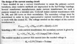
For the first bit (where he calculates the CT secondary voltage), the equation is as such:
Vct(sec) = Vsc + 2Vfwd = 1.0V + 2(0.65) = 2.3V
The 0.65V I can determine is the voltage drop across the 2 conducting 1N4148's in the CT secondary, but I can't determine what Vsc is. Is it the "current comparator threshold" in the datasheet?
If it is, I take it that it's essentially constant as the threshold voltage shouldn't change, no matter the output requirements?
For the next bit, the slope compensation resistor:
Rsc = Vosc / (2 x Isc) = (4.5 - 2.3V) / (2 * 170uA)
The 170uA was calculated previously.
So, Vosc is the "high" level of the output voltage swing?
Thanks!
I'm planning on building the current-mode halfbridge describe in Brown's book, and would like to build it "as designed" to get a feel for the math involved before modifying it for my purposes.
For the first bit (where he calculates the CT secondary voltage), the equation is as such:
Vct(sec) = Vsc + 2Vfwd = 1.0V + 2(0.65) = 2.3V
The 0.65V I can determine is the voltage drop across the 2 conducting 1N4148's in the CT secondary, but I can't determine what Vsc is. Is it the "current comparator threshold" in the datasheet?
If it is, I take it that it's essentially constant as the threshold voltage shouldn't change, no matter the output requirements?
For the next bit, the slope compensation resistor:
Rsc = Vosc / (2 x Isc) = (4.5 - 2.3V) / (2 * 170uA)
The 170uA was calculated previously.
So, Vosc is the "high" level of the output voltage swing?
Thanks!
Attachments

Yes that sounds like a good idea, especially if you already have a suitable GDT. You might have to be careful if you want to use a current transformer, it could saturate instead of detecting DC current imbalances in the circuit. With a full bridge it's easy to use a resistive shunt instead though.
What is the power level you want? A two transistor forward might be a good solution too.
What is the power level you want? A two transistor forward might be a good solution too.
- Status
- This old topic is closed. If you want to reopen this topic, contact a moderator using the "Report Post" button.