Hi,
From what I've read here (and elsewhere), for minimum leakage inductance I should wind the power transformer of a SMPS like this:
(1/2 primary)(secondary)(1/2 primary).
That is, if I need 20 turns on the primary and 10 turns on the secondary, it'll be:
(10 primary)(10 secondary)(10 primary).
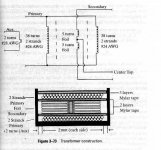
However, in Marty Brown's "Power Supply Cookbook", he shows the winding as (primary)(secondary)(primary). Thus, following my above example, the winding would be:
(20 primary)(10 secondary)(20 primary)
with the primaries connected in parallel. I've attached the figure from the book (He uses a 38 turn primary).
Is this right?
From what I've read here (and elsewhere), for minimum leakage inductance I should wind the power transformer of a SMPS like this:
(1/2 primary)(secondary)(1/2 primary).
That is, if I need 20 turns on the primary and 10 turns on the secondary, it'll be:
(10 primary)(10 secondary)(10 primary).
However, in Marty Brown's "Power Supply Cookbook", he shows the winding as (primary)(secondary)(primary). Thus, following my above example, the winding would be:
(20 primary)(10 secondary)(20 primary)
with the primaries connected in parallel. I've attached the figure from the book (He uses a 38 turn primary).
Is this right?
Attachments
Yes.
What you are trying to do is interleave the windings (n=2). The leakage inductance does is in theory reduced by a factor n^2 where n is the number of "interleavings" in your sandwich. (Bad english)
If you want minimum leakage inductance, you could do primary-secondary-primary-secondary-primary (n=3) in order to get even lower inductance. The capacitance and losses due to proximity do go up however with each level of interleaving.
The ideal construction is single layer primary, single layer secondary, single layer primary, etc...
The goal is for the primary/secondary coupling to see the same voltage potential all the way across the transformer windings.
The split winding technique does work and I do indeed use it when the other winding method can't work. This is usually because my winding window is not wide enough l(i.e. when you use RM or PQ cores).
I hope that helps.
Tony
Even though interleaving decreases the space available for copper losses will actually go down if wires are thicker than about half a skin depth! You need to look out for proximity effect losses when you are starting to approach the skin depth of the conductor. For SMSP transformers of more than maybe a few tens of watts this is almost always.
If you have a single layer primary and secondary and they both are thicker than a skin depth then current will effectively only flow on *one side* of the windings. The commonly shown picture of current flowing in a shell that gets thinner for higher frequencies is only true for a coaxial cable or similar arrangement. In a SMPS transformer it gets much worse the more layers per section.
Interleaving "splits up the middle section".
Here is a very good explanation:
http://focus.ti.com/lit/ml/slup197/slup197.pdf
The math might be a bit advanced but the pictures are pretty clear")
If the frequency is high enough (>50kHz or so I guess) then that transformer in your picture will have lower loss if thinner wire is used for the primary winding so that the wire fits in one layer per portion! The foil must be pretty thin too.
If you have a single layer primary and secondary and they both are thicker than a skin depth then current will effectively only flow on *one side* of the windings. The commonly shown picture of current flowing in a shell that gets thinner for higher frequencies is only true for a coaxial cable or similar arrangement. In a SMPS transformer it gets much worse the more layers per section.
Interleaving "splits up the middle section".
Here is a very good explanation:
http://focus.ti.com/lit/ml/slup197/slup197.pdf
The math might be a bit advanced but the pictures are pretty clear
If the frequency is high enough (>50kHz or so I guess) then that transformer in your picture will have lower loss if thinner wire is used for the primary winding so that the wire fits in one layer per portion! The foil must be pretty thin too.
- Status
- This old topic is closed. If you want to reopen this topic, contact a moderator using the "Report Post" button.