Something a little different:
I need -20.00 V DC reference voltage to apply a bias to a part of a spectrometer. The absolute precision is not as important as the accuracy: the output should remain constant within 5 mV over whatever temperature extreme the chassis would see (say 15-45 deg C) The output load is essentially infinite, i.e. >1 MOhm. Low ripple and noise are required, say 3 mV p-p max.
I'm trying to come up with the simplest way of delivering this. No reason to overbuild to extremes. A linear power supply sounds like the best route, and right now I'd looking at a LM337 negative regulator set to about -30V, an LT1009 to deliver a -2.5 V reference, and a non-inverting OP27 amplifying the reference with a gain 8. The op-amp is powered by the regulated -30 V, and the -20 V output is taken directly from the OP27. The classic regulator circuit, really, minus the pass element which is not needed since the the current output is less than 1 mA.
I'm just wondering if I'm missing anything obvious: a simpler way to get the output, or a flaw in my design.
/rjm
I would use one TL431.
It is one small IC that is used like a zener diode,
but with much, much better specifications.
It is easily adjustable from 2.5 - 36 Volt.
Using 2 resistors to multiply the 2.5V.
As with a zener diode, you use one resistor to set/provide bias current.
(You can use one Constant Current Source to feed it, if the power supply has large voltage variations.
One JFET + resistor makes a perfect CCS. But this is normally not needed.)
A very useful IC, no matter if you need positive or negative reference voltage.
For example used in a dual regulated supply. (Instead of LM317/LM337)
TL431 does not cost much. Comes in TO-92 three pin and there are SO8 packages, too.
50 ppm/C temp coefficient typical. (0.005% per degree C)
Works at 1.0 - 100 mA, max 0.7Watt
The noise is below +- 10uV
Datasheet from Texas Inst. http://focus.ti.com/lit/ds/symlink/tl431a.pdf
Several other manufacturers OnSemi, SGS-Thomson, Fairchild
The easiest way to this is indeed a linear supply, with a touch of CRC filtering then a couple of 10.0v references connected in series. Have a look through the Maxim, Linear tech or NatSemi websites will find you nice parts, cheaply, that will easily meet or exceed your spec, bott on voltage and temp stability.
There's nothing wrong with using the OP27 to multiply a reference; but it may not be needed, either; and accuracy in all parameters will suffer when compared with a higher reference voltage and less gain. If the loa dtruly is that high impedance there's no need for the buffering.
There's nothing wrong with using the OP27 to multiply a reference; but it may not be needed, either; and accuracy in all parameters will suffer when compared with a higher reference voltage and less gain. If the loa dtruly is that high impedance there's no need for the buffering.
Linear Tech put out a "Voltage Reference" whitepaper AN-42 -- you can get it off their website.
http://www.linear.com/pc/downloadDocument.do?navId=H0,C1,C1154,C1002,C1243,P1677,D4133
Shameless Plug Department -- I have a tube of REF01CN8 10V/0.3%/5ppm on my webstore -- here's the PDF -- http://www.linear.com/pc/downloadDocument.do?navId=H0,C3,P2161,D13297
http://www.linear.com/pc/downloadDocument.do?navId=H0,C1,C1154,C1002,C1243,P1677,D4133
Shameless Plug Department -- I have a tube of REF01CN8 10V/0.3%/5ppm on my webstore -- here's the PDF -- http://www.linear.com/pc/downloadDocument.do?navId=H0,C3,P2161,D13297
That's for all the helpful replies.
A couple of the suggestions I had thought about and discarded before writing my post. Looking back on it, though, they would have probably worked fine:
I was unsure if/how the TL431 could be configured for negative output.
I chickened out with the stacked 10V references too as I wasn't sure if the parts could safely be used like that.
For the record, I think both would have worked, especially the latter, which would also have been the simplest.
In the interests of going with what I know, it's the LM337L, LT1009 and OP27.
While I do realize that operating the opamp at higher gains results in a performance penalty, the resulting lower bandwidth should also make it more stable.
I have the parts and will be building it shortly. I'll post back to let you know how it went.
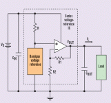
The basic schematic (for a positive voltage) is as shown:
A couple of the suggestions I had thought about and discarded before writing my post. Looking back on it, though, they would have probably worked fine:
I was unsure if/how the TL431 could be configured for negative output.
I chickened out with the stacked 10V references too as I wasn't sure if the parts could safely be used like that.
For the record, I think both would have worked, especially the latter, which would also have been the simplest.
In the interests of going with what I know, it's the LM337L, LT1009 and OP27.
While I do realize that operating the opamp at higher gains results in a performance penalty, the resulting lower bandwidth should also make it more stable.
I have the parts and will be building it shortly. I'll post back to let you know how it went.
The basic schematic (for a positive voltage) is as shown:
Attachments
I started from scratch. Ditched the voltage amplifier entirely and will go with stacked references instead.
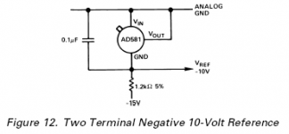
The circuit starts with 24V secondary and rectifier diodes, capacitor, feeds an LM337L adjusted to -30V, runs through a mild CRC filter to attenuate high frequency noise, and then a 3.3k resistor followed by two AD581 10V references in series, connected as per the datasheet for two terminal "zener" operation.
The AD581 is expensive, the highest grade cost me $35 each, but should do the job admirably.
I there any issue with stacking multiple references in series? I guess I'll find out...
Attachments
rjm said:The AD581 is expensive, the highest grade cost me $35 each, but should do the job admirably.
Did you try Digikey or Jameco -- they are much less than that unless you order the MILSPEC version.
You are correct, AD581LH-ND is only $20 at digikey. Its a locality thing: RS gives me next day service, no minimum order, and very cheap shipping. Digikey sends everything from the states, there's additional paperwork, and shipping is a lot more, even if I avoid the minimum order fee.
Anyway, built the circuit this afternoon and it works as specified, up to my ability to measure it anyway.
Still not sure whether having 220uF of output capacitance is a good or a bad thing, but its perfectly stable with it there so I am tempted to leave it.
Attached Eagle sch and brd files. I did the board point-to-point, so the board layout is just as a guide for me when soldering.
/R
Attachments
- Status
- This old topic is closed. If you want to reopen this topic, contact a moderator using the "Report Post" button.
- Home
- Amplifiers
- Power Supplies
- Negative Reference Voltage