Hi everybody,
i would like to use a good shunt power supply to power up the phono stage i am building.
I was thinking of using the Borbely PSU.
The schematic is attached.
I can't fully understand how it works though.
I have tried to reason over it for a long time without really catching how come i can regulate the output voltage.
I will describe what i have understood and you guys can correct me and/or add something:
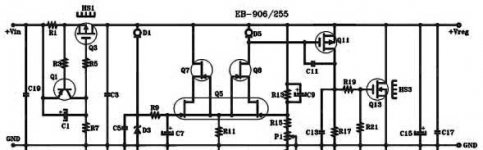
Q3/1 and surrounding parts are the CCS that sources the maximum output current.
D3 is the voltage reference for the shunt and is powered through the current control diode D1.
Q5 is the differential amplifier and Q7/8 are the cascoding.
D5 is another current control diode or active load that i guess is used to increment the gain on the Diff Amp.
R13/15 and P1 are the voltage divider supposedly used to set the output voltage.
Q11/13 are the shunt devices.
My question is: how is the output going to change when P1 is adjusted?
Second how do i chose the resistor's value?
Is anybody so kind to give help me out?
Thanks for the attention.
Best,
Stefano.
i would like to use a good shunt power supply to power up the phono stage i am building.
I was thinking of using the Borbely PSU.
The schematic is attached.
I can't fully understand how it works though.
I have tried to reason over it for a long time without really catching how come i can regulate the output voltage.
I will describe what i have understood and you guys can correct me and/or add something:
Q3/1 and surrounding parts are the CCS that sources the maximum output current.
D3 is the voltage reference for the shunt and is powered through the current control diode D1.
Q5 is the differential amplifier and Q7/8 are the cascoding.
D5 is another current control diode or active load that i guess is used to increment the gain on the Diff Amp.
R13/15 and P1 are the voltage divider supposedly used to set the output voltage.
Q11/13 are the shunt devices.
My question is: how is the output going to change when P1 is adjusted?
Second how do i chose the resistor's value?
Is anybody so kind to give help me out?
Thanks for the attention.
Best,
Stefano.

Choooookkyy,
I notice you are evveeerryyyywhheereeee, just like the supreme!!!
Interestinggg!!
On the cookbook actually this is not really explained otherwise i wouldn't be asking, would I?
What i am sure is written on the cookbook though is the phrase:
"Ask what you must ask and no simple stone will be left unreturned"
I will take the suggestion of Jan and try to write to Borbely.
For Zen:
If you have noticed ,my description matches what's described on your cookbook.
What i am missing though, is the mechanism that regulates the voltage when P1 is adjusted.
Q13 is the shunt device and eats more or less current (and if you noticed i had understood this already) but the question is:
where will the voltage drop accordingly to this variation and thus vary the output voltage?
Apparently it will have to drop across the only series element of the circuit: the CCS.
But i can't catch the mechanism.
I mean the CCS sources a certain amount of current independently of the Voltage applied to the drain of Q3 as long as this is 0.7-0.8V higher than Vin.
Voltage drop on R1 is always 0.65V.
So i am certainly missing a part.
If you can answer to this i would be thankful.
Stefanoo
don't take me wrong :
I know that I'm dumb , and more I know - I more know how dumb I am ......
do you know how dumb are you ?
everything is explained right here :
http://www.borbelyaudio.com/psshunt.asp
(and you again forgot to attach schematic )
so - I'll attach it (cropped to upper half , for your convenience)
Papa Borbely wrote it on entire page , pretty clear .
it's written where is voltage reference , and what's mechanism of operation ;
re-read ....... anyway - with my level of Engrish and Italian , I can't explain better .... frankly - Papa Borbely is a king of education , besides other things
Attachments
An externally hosted image should be here but it was not working when we last tested it.
The constant current have 2 ways to goto GND.
1. The Load
2. Q11 + Q13 = The Shunt
Suppose CCS = 100 mA
And Load takes 50 mA. And Shunt is driven by Q5+Q8 to take 50 mA to GND.
If Load suddenly takes only 30 mA, the extra 20 mA will try to escape via the Voltage sense divider = R13+R15.
Here comes the Negative feedback to GATE of Q5+Q8.
The added current will lift GATE of Q5.
JFET will drive harder and increase the Volt G-S of Q11,
which drives more current through Q13, The Shunt.
When Shunt passes 70 mA to GND and The Load 30 mA,
the current and voltage across R13+R15 is the same again. (Almost, give or take a few mV).
The voltage across R15(+P1) = Vref.
Current in R15 = Current in R13.
And so, the voltage across these 2 resistors are propotional to their Ohm value.
The output voltage stays:
VoltR13 + VoltR15
(R13 / R15 x Vref) + Vref
- Status
- This old topic is closed. If you want to reopen this topic, contact a moderator using the "Report Post" button.