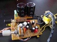
I'm tweaking a little tea2025 based amp found in a pair of pc speaker. Basically I'm playing with better caps, increasing capacitance, bypassing etc. Filter cap after diodes bridge was 1000uf, I put two 4700uf: the sound became fuller, with good bass but the little transformer (9VA-0,015a) heat too much. This is the first time I play with AC and transformers  Do bigger caps require bigger transformer? Maybe a 12v toroidal with a 7809 for regulated supply after filter caps but how choose it?
I'm sorry I know I miss some basics... any help will be very appreciated
Cheers
Do bigger caps require bigger transformer? Maybe a 12v toroidal with a 7809 for regulated supply after filter caps but how choose it?I'm sorry I know I miss some basics... any help will be very appreciated
Cheers
Attachments
The bigger capacitors needing to be charged will put more load on the transformer while at the same time preventing the rails sagging as much thus allowing the chip to provide more power to the load, thus taking even more out of the transformer.
Ciao Calamaro
Too much capacitance in the power supply is not a good idea. Increasing capacitance causes shorther charging time, and bigger peak current in the trasformer and trough the diodes.
A single 4700uF is enough.
Too much capacitance in the power supply is not a good idea. Increasing capacitance causes shorther charging time, and bigger peak current in the trasformer and trough the diodes.
A single 4700uF is enough.
Hi,
You increased the filter capacitor by ~ x 10 ?
and you do not expect trouble ?
2 x 4,700uF is just silly for a 5W max chip.
2,200 to 3,300 maximum I would say.
🙂/sreten.
You increased the filter capacitor by ~ x 10 ?
and you do not expect trouble ?
2 x 4,700uF is just silly for a 5W max chip.
2,200 to 3,300 maximum I would say.
🙂/sreten.
About the 7809: with a 12V trafo, you'll have a lot of heat from the 7809..... it need a big heat-sink
ps: your TEA2025 is not an HiFi chip.
some improvements:
-better and larger outputs caps on pins 15 and 2 (datasheet suggests 470uF, a 2200uF should give you better bass)😎
-better input caps (polipropylene?) on pin 10 and 7
ps: your TEA2025 is not an HiFi chip.
some improvements:
-better and larger outputs caps on pins 15 and 2 (datasheet suggests 470uF, a 2200uF should give you better bass)😎
-better input caps (polipropylene?) on pin 10 and 7
acid_k2 said:About the 7809: with a 12V trafo, you'll have a lot of heat from the 7809..... it need a big heat-sink
Ciao Acid_k2:
I don't understand: to have 9v from a regulator I need about 3 more v input then 12?
ps: your TEA2025 is not an HiFi chip.
in fact this is a little funny project started as a joke as I would try to use this pcb found in a dismantled pcspeaker for listen to my mp3player. My aim is to learn something new for a bigger next project
some improvements:
-better and larger outputs caps on pins 15 and 2 (datasheet suggests 470uF, a 2200uF should give you better bass)😎
I use 1000uF there isn't enough room for bigger caps/bypassed with WIMA mkt 100nF
-better input caps (polipropylene?) on pin 10 and 7
I use 1uF WIMA MKS02
Ok, so as a filter cap I'll take just one 4700uF cap: but what about a new tx?
Hell,
do the maths.
For regulated 9Vdc use a 10Vac or 11Vac transformer. If you can't find either then use 12Vac.
The regulation of a tiny transformer can approach 30%.
Your 10Vac becomes 10*1.414*1.3 = 18.38Vdc on no load.
Subtract the diode loss of the rectifier and that leaves 17Vdc to feed the regulator.
Now subtract the ripple on the smoothing caps and subtract the sag under load. Finally subtract the regulator drop out voltage at the maximum current you intend to draw. Is this final voltage more than 9V?
Hallo AndrewT, the maths are my problem  (I'm studying literature...)

(I'm studying literature...)
Your 10Vac becomes 10*1.414*1.3 = 18.38Vdc on no load
You are going the wrong way. You are doing mostly irrelevant modifications to a piece of junk and imagining the results.
If you really want to learn and have fun, consider building a bigger amplifier with a pair of chip amps (like LM3886 or TDA7294) and a pair of 2-way speakers with 6,5" woofers.
If you really want to learn and have fun, consider building a bigger amplifier with a pair of chip amps (like LM3886 or TDA7294) and a pair of 2-way speakers with 6,5" woofers.
AndrewT said:Hell,
do the maths.
For regulated 9Vdc use a 10Vac or 11Vac transformer. If you can't find either then use 12Vac.
The regulation of a tiny transformer can approach 30%.
Your 10Vac becomes c*1.3 = 18.38Vdc on no load.
Subtract the diode loss of the rectifier and that leaves 17Vdc to feed the regulator.
Now subtract the ripple on the smoothing caps and subtract the sag under load. Finally subtract the regulator drop out voltage at the maximum current you intend to draw. Is this final voltage more than 9V?
Calamaro,
10V AC (from trafo) --> (2*10*1.414) V Peak to peak;
after ideal rectifier (with 0 voltage drop) --> 10*1.414 V;
after a real rectifier (with 1.5V voltage drop on the diodes) and some capacitance --> (10*1.414)-1.5 V = 12.64V DC.
ALL VOLTAGE on NO-LOAD CONDITIONS
note:
AndrewT add another 30%.... I suppose that very small tranformers have an higher output voltage for obtain nominal voltage under load, but I'm not sure.
UNDER LOAD, I normally use 1.25 instead of 1.414 (square root of 2), so DC voltage is:
(10*1.25)-1.5=11V DC (you could use it without voltage regulator)
If you add a 7809 (about 2V drop):
11-2=9V DC (it means minimal losses in the regulator)
Grazie acid_k2. Yesterday I read something about transformers so I can appreciate your explanation. Thank you.
May I ask you just another question? One thing isn't still clear to me. If the original tiny transformer has 0.15mA output and now with bigger capacitors runs hot, do I have to increase that value? How can I reckon it? Yesterday I found a nice trasformer from an old Commodore computer, I think it has 9V - 1A output (please see pic...). Could I use it for my circuit as external tx? I would add a 7809 regulator.
Probably it's a silly question so I apologize, but I'm just approaching electronic - starting from a very very far point... So I can learn something even from "this piece of junk" 😉 and definitily I'm not feeling ashamed.
Attachments
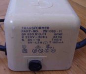
that looks like two outputs: an AC 9V output and a DC 5V output.
Measure each on zero load and measure the mains voltage (carefully) for your test condition and come back with the results.
Measure each on zero load and measure the mains voltage (carefully) for your test condition and come back with the results.
 , and watch inside.
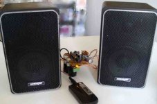
It has 5,41 DC and 10,3 AC. So if I take the AC output (regulated with 7809) I can drive 9vx1A=9watt? TEA2025B has a power output (9volt/8ohm) of 1.3 watt per channel. Could it works? And how about speaker power? I mean, I have a pair of very little but powerful speakers (50w); the little amp is driving them with no problems...
ps. now actually the tiny original transformer (0.15A) doesn't run particularly hot.
ps. now actually the tiny original transformer (0.15A) doesn't run particularly hot.
Attachments
Thank you. I'll dismantle the circuit and I'll rebuild it on a stripboard (very instructive...). I don't feel yet ready to meet my Gainclone... but in the meantime I've ordered some LM386 and TDA1552 to play with.
Thank you all again.
Thank you all again.
I've opened the Commodore transformer: obviously I found a pcb with a diode bridge, a filter capacitor, a 7805 regulator... I've removed it.
Now I have just a 9vac output/1a. Perfect for my needs.
Not bad for the pricey amount of 3 euros...
Now I have just a 9vac output/1a. Perfect for my needs.
Not bad for the pricey amount of 3 euros...
pcb for TEA 2025
Calamaro ,
I have build headphone amplifier using TEA 2025 and I can help you with PCB 🙂 http://freepdfhosting.com/eb8234668b.pdf Regards alex mm
Calamaro ,
I have build headphone amplifier using TEA 2025 and I can help you with PCB 🙂 http://freepdfhosting.com/eb8234668b.pdf Regards alex mm
- Status
- Not open for further replies.
- Home
- Amplifiers
- Power Supplies
- Better transformer for a very little amp project