Hi everyone,
I'm planning to build a 300W half bridge smps:
Specifications:
input : 230V AC 50Hz
output : +- 30V 5A
ETD 39 core (or 50mm toroid core)
FET (IRF 730) switching @ 50kHz
TL494 controller (12V supply)
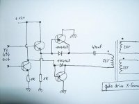
1:1:1 gate drive transformer
I would like to know if these waveforms (gate drive transformer) are ok.
advices are welcome !!
gate drive transformer core is about 26mm X 19mm X 5mm
Ac = 0,228 cm2
Np=Ns1=Ns2=22 turns
Bmax around 120mT
Thanks.
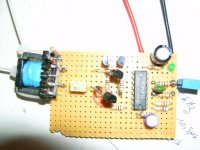
transformer driver schematics
I'm planning to build a 300W half bridge smps:
Specifications:
input : 230V AC 50Hz
output : +- 30V 5A
ETD 39 core (or 50mm toroid core)
FET (IRF 730) switching @ 50kHz
TL494 controller (12V supply)
1:1:1 gate drive transformer
I would like to know if these waveforms (gate drive transformer) are ok.
advices are welcome !!
gate drive transformer core is about 26mm X 19mm X 5mm
Ac = 0,228 cm2
Np=Ns1=Ns2=22 turns
Bmax around 120mT
Thanks.
transformer driver schematics
Attachments
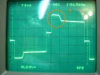
I am not the best with transformers. But I recognize it as flyback.
The explanation is that when the drive was low and then went into grounded mode, the magnetic field in the core was persisting. When the drive went to high, the clamping action ceases and the voltage can flyback during the collapse of the magnetic field.
The voltage level on the winding drops down to the power supply level once the magnetic field has collapsed. Then the power supply holds it at the lower level and builds up the magnetic field in the opposite direction as current level in the winding increases in a quite linear manner.
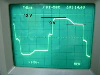
across the emitters the signal is a perfect 0-12V rectangular waveform,but across primary the signal is the same as secondary with a kind of distorsion at the top (not a flat line but no oscillation)
ps : added diodes to the bus and ground now the signal is better : always under vcc...
ps : added diodes to the bus and ground now the signal is better : always under vcc...
may be a low impedance totem pole output for the transformer is better, not sure but scope trace may be caused by leakage inductance , i guess the primary must be shorted to ground through totem pole in dead time so the core get reset, why not try SG3525 can be use with gate xfo with out a totem pole,
- Status
- This old topic is closed. If you want to reopen this topic, contact a moderator using the "Report Post" button.
- Home
- Amplifiers
- Power Supplies
- Correct gate drive waveform ?