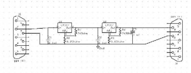
I want to design a voltage regulator to step down voltage from 70V to 20V using two LM317T chips.
I have successfully step down the voltage using the circuit design attached with this thread.
The design works fine when i test it but after loading the circuit by drawing current of about 0.2A the voltage output did not stay stable as it drops from 19.85V and below. Is there a way to regulate the voltage better as in any additional design consideration and modification needed for this design?
Please help and I would really appreciate the feedback from the LM317T gurus
Attachments
There is a datasheet about lm317 on higher voltages .
http://www.national.com/ms/LB/LB-47.pdf
I used this setup several times but the amount of amperes didn't have to be big for me .
Also i did more or less the same with the classic transistor setup .
Works good aswell (again i used it for small powers)
From the plus > base & collector resistor connected to a tip51 or some high voltage transistor .
From the base-resistor junction a zener to minus .
From the emiter (i did it through a diode) to the lm317's input .
But then again it all depends on what amperage you need .
With lets say 70 volt in 20 out @ 200 mA ,your transistor will have 50 volt between C & E @ 200 mA that means 10 Watt in heat .
Cheap ,reliable and simple but not applyable with higher amperage
Good luck .
What current are you trying to draw? Are the 317s heatsinked (and isolated!?) Sounds like one of them is going into thermal shutdown ... "warm to the touch" anywhere? ")
Besides, the whole thing is not safe when short-circuited. If you really want to do this in a linear circuit, burn up the excess volts (x amps) using a simple power transistor + zener pre-regulator, or the much nicer circuit from the appnote mentioned.
In any case, make sure you check the power dissipation involved. For more than, say, 200 mA, a simple step-down switched regulator would make you much happier.
Hi,
the first reg (U1) drops down to ~44V.
the second (U2) drops down to ~20V.
This is nearing the limits of 317 specification.
Now look at dissipation.
200mA times Vdrop is very hot.
Read the datasheet, again and again and again.
As an aside, how fixed is the 70V supply voltage?
Does it vary with loading or with mains voltage?
What is the range of supply voltage?

- Status
- This old topic is closed. If you want to reopen this topic, contact a moderator using the "Report Post" button.