Hello
I have a working circuit on which, as an addition, I need to sense the voltage across a resistor and then translate that voltage.
However I cannot think of an easya way to do it. For example I have made a small differential amplifier where there is no voltage difference between the bases of the two transistors (by biasing them very carefully) but in order for that arrangement to work the power supply to that amplifier must be isolated from the main circuit. Similar to how we attack the multimeter terminals across a resistor and we measure the voltage drop across it, without influencing the circuit.
So I have made all resistors around my noddy differential amplifier to be 220K (perhaps I should even increase them) so that I present a high input impedance. But how do I go about providing a separate power supply to it?
The only way I can think of is to attach another winding on the transformer, and take it all the way from back there.
But of course there may be a much easier way of doing this, I cannot be the first person hitting upon this problem ?
No you aren't:akis said:
But of course there may be a much easier way of doing this, I cannot be the first person hitting upon this problem ?
http://www.google.be/search?hl=en&a...=&as_occt=any&cr=&as_nlo=&as_nhi=&safe=images
Ok after reading I see that what I am trying to do is not easy. There is talk of opto-isolators, hall-effect devices as well as high side and low side sense resistors and circuits. All of which either take their supply from what is being measured or require their own power supply. Unless I am missing something, and this would not be very unlikely as I am not formally trained in electronics, I still need a means of an independent power supply. Do I have to resort back to the mains transformer then, or is there a neater solution?
I have also wondered about this a few times. I took a quick gander and seen this figure. It looks like this IC scenes voltage across a shunt and allows current to flow from Vin through Rout to ground thus raising Vout above ground.
Or its just 2:30 in the morning and i don't know what i am talking about...hehe
Or its just 2:30 in the morning and i don't know what i am talking about...hehe
Attachments
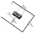
This is fine because the sense resistor is in line with the + supply rail. The diagram also does not show if the IC requires its own, individual power supply. Basically the two electrodes connecting to that sense resistor must be 100% neutral, as if they are not even there, they must not affect the voltages on the sense resistor and they must not get affected by the voltages present on that sense resistor.
PS: 7:50am here")
PS: 7:50am here
I am building a simple hFE transistor checker where the current going into the base of the transistor under test is sensed by a resistor. I can measure the voltage using my voltmeter and then do the calculations on a piece of paper, but I want an automatic way of doing that.
Fist step is to measure the voltage drop. There are more steps after that , but that would be my next question.
Fist step is to measure the voltage drop. There are more steps after that , but that would be my next question.
This can be done in a very simple manner: you need to insert a current mirror between the source for your base-bias (potentiometer, power supply..?) and the base resistor: common to the bias source, one leg to the base resistor, and the second leg is available to you and will source a "copy" of the base current into any ground (or anything) -referenced resistor.akis said:I am building a simple hFE transistor checker where the current going into the base of the transistor under test is sensed by a resistor. I can measure the voltage using my voltmeter and then do the calculations on a piece of paper, but I want an automatic way of doing that.
Fist step is to measure the voltage drop. There are more steps after that , but that would be my next question.
The base-bias source will just have to supply twice the original current.
Indeed.
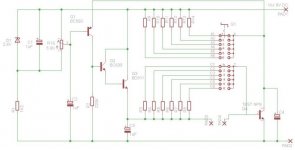
I have attached a small schematic of a current-mirror based current sensor. It was originally designed for higher currents, but if you play around a bit with the sense resistor you can achieve more sensor gain.
The block in the centre is a dual monolythic PNP transistor. This will ensure that the current mirror operates more accurately. If you can't get one, try with well matched transistors.
The two other transistors are basically just followers to supply proper output impedance.
Hope this helps.
Bakmeel
Attachments
I cannot say I understand that diagram
Here is what I have up to now. I got it off the internet and made slightl modifications to it and it seems to be working just fine (up to 80mA but planning to use it up to 5 A). This circuit uses the PNP transistor and the zener arrnagement to level off at 1V across the tested transistor's collector resistance. We then take the measurement of the voltage drop across the base resistor and that gives us the hFE at the selected collector current. The base resistor is 10x the collector resistor. Therefore hFE=10/Vb (more on this below).
I have also made a differential amplifier with a high impendance and I can amplify the voltage drop across the base resistor of the test transistor without affecting the circuit. But this amp has its own power supply (currently a battery). So I need to incorporate your suggestions into that circuit somehow (if I could understand it). Can you please explain?
Seconldy there is a more serious problem. As you see from above, hFE=10/Vb which is a parabola. But my diff. amp. amplifies linearly. How can I apply that formula electronically?
Attachments
When you want to acquire data in a certain way/format, it is generally better to start from scratch, with your requirements in mind, rather than trying to adapt a manually operated instrument.
That said, your set-up can be adapted easily: you can connect a differential amplifier with four, large resistors across your base resistor, and you'll be able to reference the output voltage anywhere.
The "normal" method would be to use a controlled current source as a base bias. This source would be servoed by the collector current, and its control voltage would directly represent the base current.
Now remains the "mathematical" problem: note that the function is hyperbolic, not parabolic.
If you intend to operate your test set with a PC or a microcontroller, the simplest option is to leave the result in its hyperbolic form until it is converted to a digital; the computation will then become very easy.
If you need the result in an analogue format, there are a number of ways to make the inversion, using log/antilog converters, analogue multipliers or time/frequency systems. It depends how accurate you want the conversion, whether you want the result displayed, etc
Yes, hyperbola, that is what I meant!
Can you please show me how to connect the diff. amplifier across the base resistor? Would that amplifier need its own power supply? (if yes, then I have already built and tested that , so don't bother)
I would like to display hFE as a result straight on a 3.5 digit display (using the 7107), very similar to attaching the multimeter across the base resistor and measuring the voltage. And I do not really care about accuracy, anything within 5% would be great. Could you please suggest a design?
PS: a colleague has just suggested using a capacitor which we let discharge and its discharge pattern may resemble a hyperbola just like the one we want?
Can you please show me how to connect the diff. amplifier across the base resistor? Would that amplifier need its own power supply? (if yes, then I have already built and tested that , so don't bother
)I would like to display hFE as a result straight on a 3.5 digit display (using the 7107), very similar to attaching the multimeter across the base resistor and measuring the voltage. And I do not really care about accuracy, anything within 5% would be great. Could you please suggest a design?
PS: a colleague has just suggested using a capacitor which we let discharge and its discharge pattern may resemble a hyperbola just like the one we want?
Look here, first circuit:
http://en.wikipedia.org/wiki/Operational_amplifier_applications
V1/V2 go across the resistor, and Rg is connected to whatever potential you want to reference the output to.
You do not need a separate supply for the amplifier, you must just make sure it accepts the common-mode voltage.
If you use a converter of the kind of the 7107, you can apply your voltage to the reference inputs, the converter will perform the inversion. See app-note. And be sure to also read carefully the explanations about the ground, the analog common, and the ways to reference the inputs.
The discharge of a capacitor is exponential, not hyperbolic; but you can use capacitors to compute the inverted value:
F.e., if you convert your value to a current which you use to charge a capacitor to a defined level, the time taken to charge the capacitor represents the inverse of the input current. You can then use this time to gate a frequency counter that will display your result.
OK, to remind you what I am doing.
I have a small circuit to measure the hFE of a transistor. I put some known current in its collector and then measure the current at the base, so hFE=Ic/Ib. In my circuit, hFE = 10,000 / Vsense, where Vsense is in mV.
The resistor across the base of the transistor under test can be up to 20K, so I figured I did not need to go to extremes in order not to load it too much. I experimented with a diff. amp consisting of 3 transistors, but in the end I settled for a TL082 op-amp because I bought a dozen of them cheap (30p each) and because I remember they were very good for audio too, so I could use them in other projects.
Now I will describe the problem I am having. The voltage measured across Rsense is not linearly proportional to the hFE so cannot be converted easily, unless one has a calculator handy and is willing to perform hFE = 10,000/Vsense all the time.
I am aiming however to be able to display the value of the hFE directly so that no calculation is needed. So I need a means of converting the curve shown below in my diagram into a straight line.
My best design has almost straightened the curve, but sadly not enough, so the error is unacceptable. I need your help to design a more accurate circuit if possible.
The following table lists:
(a) transistor type
(b) voltage drop across base resistor (in mV)
(c) hFE
(d) voltage coming out of diff. amp with ampl of about 4x
(e) voltage coming out of an inverting log amp (trying to straighten the curve)
(f) is (e) multiplied by 12x trying to rotate the line to get a 45 degree angle, so that 1mV==1hFE.
(g) is (f)+offset (4100mV) so we stay in the positive axis
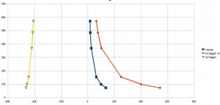
As you can see even with my best efforts the deviation from the real hFE is significant. We can play with steps (f) and (g) but the above table is amongst the best I could do based on the voltage obtained from stage 2.
Here is what the graph looks like:
I have a small circuit to measure the hFE of a transistor. I put some known current in its collector and then measure the current at the base, so hFE=Ic/Ib. In my circuit, hFE = 10,000 / Vsense, where Vsense is in mV.
The resistor across the base of the transistor under test can be up to 20K, so I figured I did not need to go to extremes in order not to load it too much. I experimented with a diff. amp consisting of 3 transistors, but in the end I settled for a TL082 op-amp because I bought a dozen of them cheap (30p each) and because I remember they were very good for audio too, so I could use them in other projects.
Now I will describe the problem I am having. The voltage measured across Rsense is not linearly proportional to the hFE so cannot be converted easily, unless one has a calculator handy and is willing to perform hFE = 10,000/Vsense all the time.
I am aiming however to be able to display the value of the hFE directly so that no calculation is needed. So I need a means of converting the curve shown below in my diagram into a straight line.
My best design has almost straightened the curve, but sadly not enough, so the error is unacceptable. I need your help to design a more accurate circuit if possible.
The following table lists:
(a) transistor type
(b) voltage drop across base resistor (in mV)
(c) hFE
(d) voltage coming out of diff. amp with ampl of about 4x
(e) voltage coming out of an inverting log amp (trying to straighten the curve)
(f) is (e) multiplied by 12x trying to rotate the line to get a 45 degree angle, so that 1mV==1hFE.
(g) is (f)+offset (4100mV) so we stay in the positive axis
Code:
Type     Vsense  HFE     Stage1  Stage2  Stage3  Stage4
BD911    136.6   73.21   543     -463    -4040   60
BC639    101.3   98.72   402     -455.1  -3970   130
2N2222A  64.9    154.08  251.4   -443.3  -3870   230
BC337    27.1    369     103.1   -420.1  -3670   430
BC550C   20.6    485.44  76.5    -412.2  -3600   500
2SC2547  17.5    571.43  64.9    -407.5  -3560   540
As you can see even with my best efforts the deviation from the real hFE is significant. We can play with steps (f) and (g) but the above table is amongst the best I could do based on the voltage obtained from stage 2.
Here is what the graph looks like:
Attachments
Continuing above post...
As you can see the yellow line is almost straight, but not straight enough.
The stage I used to make it simply has a transistor acting as a diode (collector and base tied together) on the feedback of an op-amp stage, and it does manage to straighten the curves, but I have no "adjustment" over it other than the input resistor which does not seem to affect matters much (in the way the resultnt output line is shaped).
I need something better, and I cannot help thinking that trying to do this in analogue will not work. Is there an easy way to do this digitally perhaps?
- Status
- This old topic is closed. If you want to reopen this topic, contact a moderator using the "Report Post" button.
- Home
- Amplifiers
- Power Supplies
- Independent (floating) supplies