I have an old isolation transformer rated 230V/230V 120VA with single primary/secondary windings.
Now I'm looking for a way to get +/- 150V DC @ 20mA out of it (for a tube EQ with gyrated capacitors).
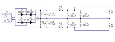
Will/would the attached circuit work or am I missing something? Should the values of R1 and R2 be lower for better performance?
A simulation of the full circuit (not just with R3/R4 a a load) suggests that the same current is drawn from both rails, so symmetry shouldn't be a problem, theoretically.
Also, would the attached circuit's ground node be a reasonable place for a star ground?
As usual, thanks for reading and replies,
David
Edit: A simulation of the attached circuit doesn't give +/-150V DC as a result, the sim is just short of +/-113V DC...it's just a simulation ...
...
Now I'm looking for a way to get +/- 150V DC @ 20mA out of it (for a tube EQ with gyrated capacitors).
Will/would the attached circuit work or am I missing something? Should the values of R1 and R2 be lower for better performance?
A simulation of the full circuit (not just with R3/R4 a a load) suggests that the same current is drawn from both rails, so symmetry shouldn't be a problem, theoretically.
Also, would the attached circuit's ground node be a reasonable place for a star ground?
As usual, thanks for reading and replies,
David
Edit: A simulation of the attached circuit doesn't give +/-150V DC as a result, the sim is just short of +/-113V DC...it's just a simulation
...Attachments
sawreyrw said:David,
... the peak of you supply is 230 volts and the RMS value is only 163 volts.
Rick
Of course
I guess I'll try it then, just have to reform the electrolytic caps and gather some other components before I will actually start building. Good thing is I already have a chassis...
thanks a lot,
dave
Edit: You think I might get away without reforming the caps? They're Epcos 470uF450V and have been in a box for maybe 4 years now (NOS...). Since they'll see only 150V...or is it too high a risk?
- Status
- This old topic is closed. If you want to reopen this topic, contact a moderator using the "Report Post" button.