Hi,
I'm using IRS2104 in a battery charger prototype like the attached file.
In continuous mode DO1 is a 5V signal with frequency=0.5Hz and duty cicle 99%(this mode is to keep the two mosfets on continuously for a max current recharging stage).
In discontinuous mode DO1 has a frequency of 100Hz and duty cicle <=50% (in this mode the two mosfets turn on and off to keep battery voltage constant).
In continuous mode everything is ok like expected.
In discontinuous mode IRS2104 became hot and then breaks after a while.
Why this happens?
Thank you!
Attachments
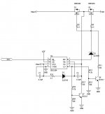
Remove R11, R13, R21, Q6 and D2, they serve no purpose other than damaging the driver IC.
The size of C8 is completely wrong. It must be capable of providing 1mA (worst case) during on time without substantial voltage drop. Increasing frequency may help a lot to keep capacitor size within practical limits. Tip: delta(V)=i*t/C
BTW: You won't get any control over battery charging rate in any of the two operation modes unless you monitor and regulate battery voltage and current (more complex circuit required). Your "discontinuous" mode will also result in substantial charging and potential overcharge and damage too.
Remove R11, R13, R21, Q6 and D2, they serve no purpose other than damaging the driver IC.
D2 is to maintain charged the two gates. Infact, in continuous mode the two mosfet are ON for more than 4sec with only one boost pulse.
Q6 is to instantly discharge the two gates because I need power from Vin.
BTW: You won't get any control over battery charging rate in any of the two operation modes unless you monitor and regulate battery voltage and current (more complex circuit required).Your "discontinuous" mode will also result in substantial charging and potential overcharge and damage too.
The circuit I have is more complex than the power stage attached. I have voltage and current monitor to recharge battery at correct rate.
Furthermore I have two power stage to recharge two battery indipendently from only one supply.
lorenzo_cy said:
D2 is to maintain charged the two gates. Infact, in continuous mode the two mosfet are ON for more than 4sec with only one boost pulse.
Q6 is to instantly discharge the two gates because I need power from Vin.
Don't expect a 100nF capacitor to provide 0.5mA or more to the high side driver during 4 seconds. It can only power it during 500us or so. Have you checked with oscilloscope that the circuit is actually doing what you think?
You don't need an external discharge network for the gates, both the low and the high sides of the driver IC are capable of charging and discharging gates alone.
Q6 is causing some reverse current to flow through the high side driver while the bootstrap capacitor is being charged. This can destroy the IC.
Remove R11, R13, R21, Q6. Short D2. Increase C8 to at least 10uF and ensure proper charging time. Increase minimum operating frequency to at least 100Hz. It will start working...
I've checked it with the oscilloscope and everything is ok. In contiunuous mode I've recharged a battery with 30A for 1 hour without problem.Don't expect a 100nF capacitor to provide 0.5mA or more to the high side driver during 4 seconds. It can only power it during 500us or so. Have you checked with oscilloscope that the circuit is actually doing what you think?
Ok, this is right but I've tried to cut VS pin to prevent reverse current and the story remained the same.Q6 is causing some reverse current to flow through the high side driver while the bootstrap capacitor is being charged. This can destroy the IC.
Now in continuous mode I've a duty cicle of 99.95% and the efficiency is high. The efficiency is much lower with 100Hz and 10uF.Increase minimum operating frequency to at least 100Hz. It will start working...
However, in new chips I measure a lots of parasitic diodes between COM and VCC, HO and VB, and others.
In broken chips I note that some of these diodes are open. These diodes are between: COM-VCC, COM-IN, COM-SD.
Probably there is a problem in the input stage.
- Status
- This old topic is closed. If you want to reopen this topic, contact a moderator using the "Report Post" button.