SMPS supplies often used to employ a large power resistor and a zener to provide the (eg 12V) for the electronics during start-up. Once the PSU was running, the 12V was supplied by an auxilliary winding on the output transformer. As the resistor only had to provide power for a few cycles it never really got hot.
That looks just fine, but what will happen when the SMPS enter protection mode?
Like over current protection, Thermal shutdown for 1 minute let say?
If the AUX circuit is poor, resistor wont hold too long. I never saw a good start up circuit
Good luck
how much output it gives and can the output transformer be wound up on a feritte round(ring) core...if yes then how many turns????????????may be you can try this, it works great. I have modified this design for +-70 and tested on a 400watts amp whihout much heating. You may be required to decrease the no. turns and gauge according to your requirement
thanks
sir i been following this topic and im interested in your design can you please share me the files of the 2 design you already made,, i have a etd44 core i want to make +/- 40 out of it can you help meFew actual photographs of the two prototypes
Hello! This project is very interesting.
 Hello! newly, Excellent project, I'm interested, Please could you send me the files too?.
Thousand Thanks.
os12300@gmail.com
Hello! newly, Excellent project, I'm interested, Please could you send me the files too?.Thousand Thanks.
os12300@gmail.com
That looks just fine, but what will happen when the SMPS enter protection mode?
Like over current protection, Thermal shutdown for 1 minute let say?
If the AUX circuit is poor, resistor wont hold too long. I never saw a good start up circuit
Good luck
Can you not use a 240VAC rated capacitor as a current limiter, with a small diodebridge, smoothing cap and a zener as a shunt regulator?
It is good for up to 50-60 mA easily continuously.
(240VAC rec = 335 VDC-12V zener = 323V DC / 50 mA = 6,5 kOhm, i e the capacitors impendance @ 50Hz => ~490 nF ,say 470nF)
This will be a much more reliable supply as no power is dissipated in the cap(well almost none) and the small power factor degradation, well...
Yes, it will be a bulky cap, but still smaller than a small tranny...
Excellent project, I'm interested, Please could you send me the files too?
Hadi.ghr.e.61@gmail.com
thanks
Hadi.ghr.e.61@gmail.com
thanks
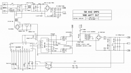
SG3525 IR2110 SMPS Question
Hello everyone,
I made this SMPS using the schematic I have attached to my message. I built it using the exact same parts written in the schematic.
The only difference is that I adjusted the circuit for +36/-36 volts. So, I used a 36v zener and as for turns ratio, (Primary 26 turns of 1.7mm ) and (Secondary 2X4 turns of .7mmX5) are my winding. (ExcellentIT calculations)
I expected everything to run smoothly but after running it, all I get in the secondary output is +/- 2 volts!!
Also the transformer makes an unpleasant noise.
What would you suggest me to do?
Thanks!
Ciro.
Attachments
Few actual photographs of the two prototypes
Pins 1 and 2 of optoisolator in your design are connected differently to the outputs comparing to the original schematic by VEYSEL. Which one is correct?
I built it but it has only 1.7 and 2.5 volts on output. Transformer also make a bad HISS noise. seems like the feedback section is not correct.
Greetings.
@kooroshi60 you don't get 36V per rail on the output just by using a 36V zener, remember that the upper limmit comes into play when the opto-isolator's LED activates the phototransistor, the photoelement needs to source about 5mA of current, and from the datasheet i estimate that the LED will need about 4,5mA, let's say 5mA to be sure, now providing that the series resistor is 510R then the voltage drop on it will be 2,55V, the LED has a forward voltage drop of about 1,1V at that current, so a total of 3,65V is added to the voltage rating of the zener, rising it up to 39,65V ( theoreticaly anyway ).
As for the power transformer, did you use ETD59 as in the schematic? As i see you have a problem with the turns ratio, you said u have 26 turns on the primary side, and 4 turns per rail on the secondary side, that makes it a 6,5 turns ratio, now with a half bridge config u have about 150V on the primary winding, divide that by 6,5 and u get about 23V, witch is way too low a voltage for the opto-isolator to do it's job, the feedback loop thus cannot work properly and that is why i think u get that noise.
What you should do is rewind the power transformer, you need to work out a low value AC line where you still want the supply to work properly, and then estimate at that line level how much voltage is lost from the point where the AC line connections are, to the primary windings, those losses are in the NTC, some in the line filter's inductor, on the rectifying bridge, losses due to the voltage ripple on the filter caps, losses to the primary series capacitor do again to the voltage ripple on it, losses on the power mosfets, all those losses need to be estimated at the maximum power required, where the primary side current is highest, and all of the losses amount to a vallue that need to be taken into account in estimating how much voltage the primary winding gets, at that voltage you need to establish a turns ratio that will ensure you get on the secondary rails just before the rectifying bridge, at least 40V ( or rather a bit more, to make sure the losses on the diodes are covered ), that is the only way you can provide enough resources for the feedback loop.
Finally, you should also need to pay some attention to the series inductor, just after the diodes, or rather to it's vallue, cus 22uH seems a bit low to me...
If you want i can do all the calculations for you, and provide some numbers that you need to work with, just tell me if there is any other differences, and also what power transformer did you use, and finally how much power it is required from the PSU?
Cheers.
Last edited:
Thanks for your help MarianB. The problem were the output coils. Those wrong labeled low quality Chinese coils wasted my time searching for the error. They were supposed to be 20 uH but in fact they were 50!!!! and that was the cause of voltage drop on outputs.
NEVER EVER TRUST CHINESE COMPONENTS OTHERWISE YOU CHECK THEM FIRST!
Ciao!
NEVER EVER TRUST CHINESE COMPONENTS OTHERWISE YOU CHECK THEM FIRST!
Ciao!
You're welcome.
Still i disagree, just a larger value inductor cannot cause the described failure, it cannot compensate for a wrong turns ratio, granted it can cause problems with feedback loop stability in some cases, but still i do not think they were the problem, if you have read what i have said earlier, then you should find that there are problems other than that, i have explained why.
Still i disagree, just a larger value inductor cannot cause the described failure, it cannot compensate for a wrong turns ratio, granted it can cause problems with feedback loop stability in some cases, but still i do not think they were the problem, if you have read what i have said earlier, then you should find that there are problems other than that, i have explained why.
Greetings @kikodemy, it is "he"
@kooroshi60 you said you want 36V per rail outputs, for that to happen with the turns ratio you have, you need at least 234V on the primary side, and that simply cannot happen with a half-bridge config. The most you can hope for is perhaps 160V at light load. You need a lower turns ratio, and you need to calculate it much more precisely given a needed voltage on the outputs, and a well estimated voltage rating on the primary side. And again, the 36V zener is too large for your intended outputs, i have already explained why in #94 posting, a 33V zener should be ok i think.
As for the output inductor, the feedback loop reads only the positive rail, the inductor needs to have both windings on the same core ( properly phased ) to get a decent amount of cross-regulation, or you will get a negative rail very poorly regulated, and thus poor performance. I think you should wind your own inductor, select 2 copper wires at the correct length and do both windings in parallel, thus obtaining the best symmetry and magnetic coupling between them, so the cross-regulation is optimum.
Good luck.
Hello everyone,
I made this SMPS using the schematic I have attached to my message. I built it using the exact same parts written in the schematic.
The only difference is that I adjusted the circuit for +36/-36 volts. So, I used a 36v zener and as for turns ratio, (Primary 26 turns of 1.7mm ) and (Secondary 2X4 turns of .7mmX5) are my winding. (ExcellentIT calculations)
Wrong. With these values you can get 21 V maximum, loaded.
I expected everything to run smoothly but after running it, all I get in the secondary output is +/- 2 volts!!
Also the transformer makes an unpleasant noise.
What would you suggest me to do?
Thanks!
Ciro.
Check feedback. First thing is checking optocoupler LED current (voltage on 510 ohm). I guess zener is connected with wrong polarity.
(But 0th step is getting an oscilloscope and -1th step is understanding basics of electronics.)
I don't see serious problems. Feedback is not very good indeed, but placing a resistor into the COMP pin can help.
Last edited:
- Status
- This old topic is closed. If you want to reopen this topic, contact a moderator using the "Report Post" button.
- Home
- Amplifiers
- Power Supplies
- -/+ 50 v SMPS