12 V 30 A
hi
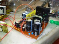
this is the pcb layout of my newly project in two part .
1st main board is power section & 2sd is PWM section
of course i used a few SMD components in PWM pcb
EDT 44
pri 36 [turn]
sec 4 [turn] " center tab "
pri wire size : 4*26 (AWG)
sec wire size : 33*26(AWG)
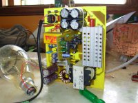
part one bottom side :
hi
this is the pcb layout of my newly project in two part .
1st main board is power section & 2sd is PWM section
of course i used a few SMD components in PWM pcb
EDT 44
pri 36 [turn]
sec 4 [turn] " center tab "
pri wire size : 4*26 (AWG)
sec wire size : 33*26(AWG)
part one bottom side :
Attachments
Dear mahmood,
I would like to build your smps(230V>+/-50V,SG3525,IR2110). Please send to me the pcb files, Thank you!
nincsmar@gmail.com
I would like to build your smps(230V>+/-50V,SG3525,IR2110). Please send to me the pcb files, Thank you!
nincsmar@gmail.com
Current Ratings.
Hi Mahmoud.
Just one question after this long discussion,
Is this power supply stable for long time operation?
have you loaded it with fixed loads for 1 hour? to draw 6 amps? 4 amps?
what is the current rating for it?
It can deliver +/-50V 6 Amp continues?
Thanks...
Hi Mahmoud.
Just one question after this long discussion,
Is this power supply stable for long time operation?
have you loaded it with fixed loads for 1 hour? to draw 6 amps? 4 amps?
what is the current rating for it?
It can deliver +/-50V 6 Amp continues?
Thanks...
Current Ratings.
Hi Mahmoud.
Just one question after this long discussion,
Is this power supply stable for long time operation?
have you loaded it with fixed loads for 1 hour? to draw 6 amps? 4 amps?
what is the current rating for it?
It can deliver +/-50V 6 Amp continues?
can you give more info about the transformer winding?
What is the meaning of 4 Turn center tap (33*0.4)
Thanks...
(33*0.4)
Olá Amigo ..........
Please, write in english only
No possible to approve posts I cannot read

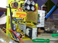
Part two component side :
Hi,
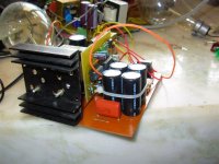
This is a fascinating design and I built it using my own layout. I would like to share it with others DIYers. I modified it for different voltages.
The design works perfect with around 500W constant load with little rise in mosfet temperature.
Controller board is same for both designs
Attachments
Last edited:
Hi,
The design works perfect with around 500W constant load with little rise in mosfet temperature.
Controller board is same for both designs
A lot of questions:
#Turns?
primary?
Secondary?
Etdxx?
awg?
tl494? or sg3525?
A lot of questions:
#Turns?
primary?
Secondary?
Etdxx?
awg?
tl494? or sg3525?
#Turns? Primary 25T 1X18#, Sec 14T 2X20# for +/- 75V~
Etdxx? EE42/42/20
tl494? or sg3525? SG 3525 + IR2110
Thanks
Hi everybody,
I am not much expertise with SMPS. I have few questions:
1. Transformer data: 25T Primary, 14 T secondary on EE/42/42/20 core.
2. Zener used 62V between 0V & + secondary voltage.
3. rest is same as mahmood schematic.
Now according to mahmoods revised schematic, the volts per turn comes to be 4.666 ( 42/9T). So the 14T in secondary should give ~65V and therefore I put 62V zener.
But my SMPS is giving +/- 78volts and this drops to Around 76 volts on connecting a 1000W halogen. Thus the SMPS is regulating the load.
Why this is happening. I think the volts per turn is incorrectly mentioned as +/-42 in place of +/-50 in the revised schematic. because if we consider 50 volts out from 9 turns, we get 5.555 volts per turn (50/9T) and this gives 78 volts for 14T.
Even if we consider 5.55 V/T, second question: why the SMPS is regulating 78 volts when the zener is 62 Volts.
Please correct If I am wrong anywhere .
Eva, could you please throw some light?
Thanks
Attachments
Last edited:
The negative output rail is not connected to the diodes properly either.
Hi EVA,
Will this schematic work. Please suggest no. of turns and wire guage for the driver transformer. This is a combination of mahmoods schematic & C Audio pulse series SMPS
Thanks
Attachments
better use an IR 2110, it is stable and reliable
best regards,
You tried that chip before?
You tried that chip before?
yes and it is quite stable.
the only problem is that you can't use it to paralel mosfets because it can drive max 2A.
best regards,
Ir2110
Correct
yes and it is quite stable.
the only problem is that you can't use it to paralel mosfets because it can drive max 2A.
best regards,
Correct
Last edited:
- Status
- This old topic is closed. If you want to reopen this topic, contact a moderator using the "Report Post" button.
- Home
- Amplifiers
- Power Supplies
- -/+ 50 v SMPS