Hi! The attached file is a schematic of 50KHz SMPS power supply which uses 325 VDC (after rectification of Mains 240 V). The required current for charging Lead Acid battery is approx 20 Amperes. Please give comment if any modification in the circuit is required. (note: isolated 12V DC is used for control circuit)
Voltage regulation is not necessary.
Voltage regulation is not necessary.
Attachments
Hi
You don't have gate resistor for each gate, say 22R, not that 4.7R, if you thinking of having it this way, replace it with 10 or 12R
I don't know those diods, just as a note, they have to be fast, say ~<100ns Trr
22uF for upper gate and lower is ok, it won't hurt you if you put 100uF, since they are only 16v
Turns on your trafo are a bit high, you can use around 30 and lower too, you will have less secondary turns, but say not less then 4 turns. PC supplys have 40 for primary and 4 to get 12v, 3 to get 5. You could lower primary number of turns and have say 5 turns for secondary. So you are looking at say 34:5+5
you will split primary into two, first half goes on core first, then both secondarys, then second half of primary in same direction that you winded first layer
You don't need 350v bulk caps, they can be 200v, and use atleast 470u, if you have chance use 4 of them, so you will have 940u for upper and lower cap(2 and 2 in ||). But single 470u will do just fine
xyz9915 , if the output (16v dc ) directly connected to battery then you need a current limited smps , otherwise your smps would explode as soon as you power it up while its connect with the battery, a 100ah-200ah battery would take more the 50amps depending on the state of charge,
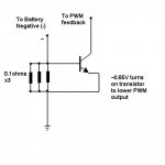
A 20A CCS can be made by having the negative side of the battery flow through three 0.1 ohm 10W resistors in parallel (0.033ohm). To get more current, just use more resistors.
Use an NPN transistor b-e to measure the drop across these resistors, and connect the collector to the feedback pin of your PWM IC chip.
When over 0.65V flows across the resistors, the transistor turns on, and pulls down the feedback voltage to lower the output voltage to keep a constant current in the resistors.
Attachments
luka said:Hi
losses would be high, and when you go up with current,30 or 40A... but it is the way to go...
But it's a battery charger, most have losses and heat, it's still not as bad being PWM instead of a linear setup. And most of the heat is all in the power resistors. Most Current limiting measures the voltage drop across a known resistance.
I wonder if a few loops of thick wire could make a good substitute for the resistors...
Hi
Yes I know, I made one, 20A linear, heavy and good heater
It would be great if we would take one more step and try to use current trafo and sense current that way, maybe use OP and then somehow affect the feedback, with no losses + you can set it to any current not just the ones you can get with resistors.
At this point I just don't know how to bring it to TL, but I think I have one OP inside still free
Wire...would work, but it would be great if independent of load and wire attached to smps
luka said:Hi
Yes I know, I made one, 20A linear, heavy and good heater
It would be great if we would take one more step and try to use current trafo and sense current that way, maybe use OP and then somehow affect the feedback, with no losses + you can set it to any current not just the ones you can get with resistors.
At this point I just don't know how to bring it to TL, but I think I have one OP inside still free
Wire...would work, but it would be great if independent of load and wire attached to smps
Great idea!!! Never thought about that!
Maybe have the output secondary winding (before the diodes) go to another toroid in series with just 2 or 3 THICK loops of wire for the primary and more turns for the secondary to feed the sense circuit. It would be similar to a primary-side current sense.
Hi
I was more thinking in the line of...you know where you have CT that goes to output GND? you would put it there, those wires could go through current sense trafo, *no turns!!* just one, more like just passing by, and have say 50 turns for secondary, 50 is not real number, one would have to be calculated. And that you would take to TL I suppose, to 16,15 and compare it with reference? Something like that. *almost 0 losses*
I was more thinking in the line of...you know where you have CT that goes to output GND? you would put it there, those wires could go through current sense trafo, *no turns!!* just one, more like just passing by, and have say 50 turns for secondary, 50 is not real number, one would have to be calculated. And that you would take to TL I suppose, to 16,15 and compare it with reference? Something like that. *almost 0 losses*
After receiving many criticism in the design, I have changed the design by using UC3842 Current-Mode PWM Controller chip. The data sheet is available with various manufacturer, while one page from http://onsemi.com is shown in the attachment. The schematic is then modified by me to fulfill my requirements. So, please point out if any further change is required.
Attachments
Hi
You are making offline smps, 16v @ 20A, best to use here is half-bridge, use SG or for that matter any IC that has dual output, use IR and you are done. There are several schemas on this forum, one of them is my. Don't try to reinvent hot water...
BTW: flyback is not good for those power levels, is it best for <100w
What about start out with some PC power supplies? There are some articles out there on how to modify a PC power supply for 13.8v output. Add another resistor to the feedback to allow it to go up to 14.4v (under logic control), add current limiting, and maybe add a blocking circuit to avoid discharge (can be as simple as a large rectifier or as elaborate as a MOSFET driven from a simple charge pump on the main transformer.
BTW, the general algorithm is to charge at limited current up to 14.4v, hold that voltage for some time (several hours), then drop off to 13.8v. For long term use, pulse it at 14.4v every once in a great while (every few months). The easiest way to get that kind of timing is to use a low frequency oscillator driving cascades of counters.
BTW, the general algorithm is to charge at limited current up to 14.4v, hold that voltage for some time (several hours), then drop off to 13.8v. For long term use, pulse it at 14.4v every once in a great while (every few months). The easiest way to get that kind of timing is to use a low frequency oscillator driving cascades of counters.
- Status
- This old topic is closed. If you want to reopen this topic, contact a moderator using the "Report Post" button.
- Home
- Amplifiers
- Power Supplies
- Help required for this SMPS Battery Charger