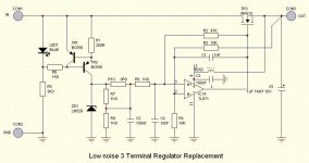
See image for schematic..
I'm just experimenting with low noise 3 terminal regualtor replacements, so comments please on my mish-mash of various exisitng ideas / designs before I go knock one up.
I think (*ahem*) I have incorporated a broadband bessel filter by using R9, C4, R2 & C1. God knows if this is a goer. Also not too sure of power source for the OpAmp. I've taken it from the 'clean' output via bead L1 a la SuperReg designs.
Oh well, have fun ridiculing me
Andy
Attachments
Have you designed this by yourself? (seems that way)
I think the worst part here is the opamp if you really plan to use TL071. The opamp has more noise than the voltage reference.
If you take supply voltage to the opamp from the output how do you plan to have a voltage at the gate of the mosfet that is 3-4 V higher than the supply voltage?
One way to find out is to use LTSpice and simulate.
Hey peranders,
Is LTSpice a freebie??
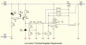
Schematic updated then....
Kind of.... have combined several ideas as it were. Thus, standing on the shoulder of giants etc. etc.Have you designed this by yourself?
What could be a better choice for the TL071?I think the worst part here is the opamp if you really plan to use TL071. The opamp has more noise than the voltage reference.
Yep - always the obvious that one tends to miss - I knew there was something not quite right there.If you take supply voltage to the opamp from the output how do you plan to have a voltage at the gate of the mosfet that is 3-4 V higher than the supply voltage?
Is LTSpice a freebie??
Schematic updated then....
Attachments
Yesunderwurlde said:Is LTSpice a freebie??
Check for example the noise. Many opamps today are significant better.
These 'super' regualators are common knowlegde AFAIK, this is just a mish & mash of other people's ideas gathered from this site & other sources in an attempt to minimize it down to a mini-super reg to a TO220 size for linear reg replacement. Granted, LC Audio do this too.
I also tried to cunningly incorporate an active filter into the design, but this idea turned out to be utter bollocks when I modelled it in MultiSim...
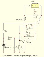
Update:
I also tried to cunningly incorporate an active filter into the design, but this idea turned out to be utter bollocks when I modelled it in MultiSim...
Update:
Attachments
That design would have a high dropout voltage as the MOSFET gate must be driven to 5v or so above the output at high load. Either run the opamp from a higher voltage supply or change the design to use a P-type MOSFET.underwurlde said:These 'super' regualators are common knowlegde AFAIK, this is just a mish & mash of other people's ideas gathered from this site & other sources in an attempt to minimize it down to a mini-super reg to a TO220 size for linear reg replacement. Granted, LC Audio do this too.
I also tried to cunningly incorporate an active filter into the design, but this idea turned out to be utter bollocks when I modelled it in MultiSim...
Update:
- Status
- This old topic is closed. If you want to reopen this topic, contact a moderator using the "Report Post" button.
- Home
- Amplifiers
- Power Supplies
- Low Noise 3-Terminal Regualtor