Hi,
I found an older PSA-4033 power supply laying around, and I took it for a closer inspection. Since it is rather simple, flyback-based design, it wasn't a big deal to figure out the schematics and component values as well. I did contact the manufacturer, however, since I'm planning to build another quite similar power supply based on this one. The corrected schematics is attached to this message, labeled "psa4033.pdf".
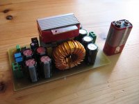
Previously I found an article on simple boost converter from the well-known Elektor-magazine. I did build one following the article as closely as I could, using mostly components I already had. The schematics and some photos are also attached to this message. If you look at the pictures, note that the red tape is for mechanical support, as it binds the heat sinks (separated by a pice of cardboard) together. The smaller heat sink is for the double diode, I did remove it afterwards to improve the efficiency (the forward voltage drop decreases with rising temperature as we know). I did not measure the coil resistance properly, but my DMM gave about 0.3 ohms and that was quite enough for me. It turned out to be much lower, since the efficiency of this converter is quite close to 92 % at 60 W output. The coil resistance is the most governing factor in efficiency as far as I know (concerning this converter). Oh, and the input/output voltages are 12/19 - this converter should be able to feed my laptop from a 12 V car battery.
Finally to my questions: I'm planning an off-line flyback for my laptop, it should give 19 V @ 5 A. I've used some time reading the "Fundamentals of power electronics" by Erickson et al. and now I am somewhat aware of the design procedure. The major problem is the flyback transformer, or the coupled inductor, which way you like it. I found some design formulae on the book, but can I trust them? It seems that ELFA is selling some suitable ferrite cores (ETD type), which I could use.
The second one: Is it possible to use zener regulator to make the supply voltage for the controller circuit? Ok, The other option is to add auxiliary winding to the transformer.
I have taken several courses in the university concerning power electronics, so I do understand the PSA-4033 schematics quite well, for example. I am aware of the required snubber and protection circuits. But still, can I build a 95 W PS based on the PSA-4033 schematics and layout? I think I can, but I would like to hear some comments, since there are some seemingly experienced designers here. Thanks for your help!
I found an older PSA-4033 power supply laying around, and I took it for a closer inspection. Since it is rather simple, flyback-based design, it wasn't a big deal to figure out the schematics and component values as well. I did contact the manufacturer, however, since I'm planning to build another quite similar power supply based on this one. The corrected schematics is attached to this message, labeled "psa4033.pdf".
Previously I found an article on simple boost converter from the well-known Elektor-magazine. I did build one following the article as closely as I could, using mostly components I already had. The schematics and some photos are also attached to this message. If you look at the pictures, note that the red tape is for mechanical support, as it binds the heat sinks (separated by a pice of cardboard) together. The smaller heat sink is for the double diode, I did remove it afterwards to improve the efficiency (the forward voltage drop decreases with rising temperature as we know). I did not measure the coil resistance properly, but my DMM gave about 0.3 ohms and that was quite enough for me. It turned out to be much lower, since the efficiency of this converter is quite close to 92 % at 60 W output. The coil resistance is the most governing factor in efficiency as far as I know (concerning this converter). Oh, and the input/output voltages are 12/19 - this converter should be able to feed my laptop from a 12 V car battery.
Finally to my questions: I'm planning an off-line flyback for my laptop, it should give 19 V @ 5 A. I've used some time reading the "Fundamentals of power electronics" by Erickson et al. and now I am somewhat aware of the design procedure. The major problem is the flyback transformer, or the coupled inductor, which way you like it. I found some design formulae on the book, but can I trust them? It seems that ELFA is selling some suitable ferrite cores (ETD type), which I could use.
The second one: Is it possible to use zener regulator to make the supply voltage for the controller circuit? Ok, The other option is to add auxiliary winding to the transformer.
I have taken several courses in the university concerning power electronics, so I do understand the PSA-4033 schematics quite well, for example. I am aware of the required snubber and protection circuits. But still, can I build a 95 W PS based on the PSA-4033 schematics and layout? I think I can, but I would like to hear some comments, since there are some seemingly experienced designers here. Thanks for your help!
Attachments
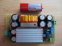
Thanks. I'll put the bottom copper side and assembly pictures here as well, in case someone would like to build this small but furious boost converter. The following files should be self-evident, but pay attention to the pin configurations and component polarities.
Attachments
Well I guess you can design a boost converter rated 1 kW, but think about the currents involved. The inductor current ripple would be enormous unless the inductor itself is designed to be large enough. I wouldn't personally try such design.
But if you need that 14,4 V @ 100 A converter, a full-bridge (buck-derived) topology could be your choice. That would mean an off-line project, naturally.
Check this site:
http://schmidt-walter.eit.h-da.de/smps_e/smps_e.html
If you are familiar with Matlab (=if you have it), I wrote a small m-file with which a boost converter can be analysed. The model includes several lossy elements, such as coil resistance, diode forward voltage drop (and its forward resistance) and mosfet on-state resistance. The m-file is still under development, but it gives somewhat correct answers. Feel free to try it and post comments!
Here it is:Boost m-file
Hi,
yes, Rl is the wire resistance. If you look at the code, you'll note that you can modify the axis limits. I used logarithmic y-axis in the power graph and the limits are 1 W <-> 100 W. Try setting the minimum point (ymin) to 0.01 W for example.
semilogy(D,Ptot)
grid
axis([0 1 1 100])
The limits are in the parentheses, axis([xmin xmax ymin ymax]).
EDIT: Sorry, you have to raise the maximum power limit to 1000 with the chosen values. It seems that by using these values, the converter would dissipate more than 100 W in any case.
Hi,
I'm not sure how familiar you are with the math behind these converters, but if the duty cycle approaches 100 %, the output voltage indeed goes to zero and the power losses raise very much. That's due to the losses within the converter.
I don't have similar code for push-pull, although I could write one in the following weeks. By the way, I have one JavaScript calculator for the boost as well, check if it is of any help")
Boost calculator
EDIT: Well, it seems the calc isn't working properly, I'm fixing it.
E2: Insert the duty cycle as 0.X, not as X %. So 50 % = 0.5
I'm not sure how familiar you are with the math behind these converters, but if the duty cycle approaches 100 %, the output voltage indeed goes to zero and the power losses raise very much. That's due to the losses within the converter.
I don't have similar code for push-pull, although I could write one in the following weeks. By the way, I have one JavaScript calculator for the boost as well, check if it is of any help
Boost calculator
EDIT: Well, it seems the calc isn't working properly, I'm fixing it.
E2: Insert the duty cycle as 0.X, not as X %. So 50 % = 0.5
If boost converter is driven with 100 % D.C., then there is only the inductor and the on-state switch in series with the input voltage. Therefore the current drawn from the input is defined only by the coil resistance and the on-state resistance. If these resistances make 0.1 ohm total, they will draw 120 A from a 12 V supply. Then the total power loss becomes 1.44 kW at steady-state.
I'll look at the push-pull code if I have time. Nice chatting with you!
I'll look at the push-pull code if I have time. Nice chatting with you!
- Status
- This old topic is closed. If you want to reopen this topic, contact a moderator using the "Report Post" button.
- Home
- Amplifiers
- Power Supplies
- Some experiments with switching power supplies