
tricky...
The answer is found by 1 of two means:
1) Check the manufacturers website for colour codes...;-)
2) Assuming you know which pairs correspond to each of the secondaries, you connect one wire from each pair together, then you measure AC voltage across the other pair...be careful not to short as you are measuring or it may get 'exciting'.
if the voltage you measure is close to twice the rating of one of the secondaries you have them in series...ie the 0 is the junction of the two secondaries and the rectifier is fed from the ends you measured the 2x voltage from.
If the voltage you measure is more or less zero, you have them in parallel, swap the ends of ONE of the secondaries and try again...
While you are 'discovering' connections in this way a good tip is to wire a 40-60W light bulb in series with the primary, it makes the effects of accidental shorts much less dangerous and acts as an error indicator...
Stuart
yes always use the light bulb, even when you think you know how to wire it up.
Wire each of the transformer wires to an insulated terminal strip.
Switch on and if the bulb stays out, measure the voltages at the primary and at the secondary.
switch off.
Add a jumper link between a pair of secondaries.
Switch on. Is the bulb still off? if it's on switch off. You have just shorted a secondary winding.
Yes, it's that simple to experiment safely.
Andrew,
Any chance you could show such a setup in a schematic or wiring diagram? AC plug->light bulb-> insulated terminal strip with a generic transformer attached? Super-noob here with multiple salvaged audio amplifier transformers that I need to measure to find their rating. I'm building dx amps with as many recycled parts as possible. Any advice, links, diagrams, etc would be appreciated.
best wishes,
Brian
Hi,quoydoy said:Any chance you could show such a setup in a schematic or wiring diagram? AC plug->light bulb-> insulated terminal strip with a generic transformer attached? Super-noob here with multiple salvaged audio amplifier transformers that I need to measure to find their rating. I'm building dx amps with as many recycled parts as possible.
start searching. There are a few schematics showing how to wire up a plug top, bulb holder and socket outlet.
Don't even think about trying to measure the VA rating of your transformers. You don't know whether the manufacturer specified them by maximum temperature or maximum voltage drop or some other combination of limiting parameters.
You can measure the wire diameters to gain an insight to the maximum continuous AC current available from each winding and you can measure the open circuit voltages of the various windings.
You could even try a short terms test (1S or 2S) to see how low the voltage drops on each of the winding at those typical Max AC currents but you need to load up ALL the windings simultaneously just to measure each one in turn.
The transformer will heat up quite quickly during this test so allow plenty of cooling down time between each test/reading
Wasn't there a guideline about VA rating and the physical weight of the toroid?
Of course this is inaccurate, but it gives a quick thought of the usefulness without measuring. Just keep it on the save side when using this method.
http://www.diyaudio.com/forums/showthread.php?s=&threadid=7492
and
http://www.diyaudio.com/forums/showthread.php?postid=1294796#post1294796
Bart.
Of course this is inaccurate, but it gives a quick thought of the usefulness without measuring. Just keep it on the save side when using this method.
http://www.diyaudio.com/forums/showthread.php?s=&threadid=7492
and
http://www.diyaudio.com/forums/showthread.php?postid=1294796#post1294796
Bart.
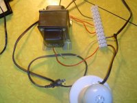
Attached is my test setup for a xformer from a Kenwood KA-3500. Approximately 35-40 watt amp.
All five leads from the xformer attached to an insulated terminal strip. Light bulb in series with the primary.
Is this test set up ok? I'll turn this on with a surge protected fused power strip.
Pic attached.
(3rd try to post here tonight...)
Thanks for your consideration.
best wishes,
brian
All five leads from the xformer attached to an insulated terminal strip. Light bulb in series with the primary.
Is this test set up ok? I'll turn this on with a surge protected fused power strip.
Pic attached.
(3rd try to post here tonight...)
Thanks for your consideration.
best wishes,
brian
Attachments
Hi
Take the opportunity to ask a similar question.
With two sec windings 0-35V 0-35V, witch ones am i going to put together 35-(0 0)-35 or 0-(35 0)-35 ?
Is this transformer a good choice for hifi ? I have 230V in house.
Think i have some drop on the secondaries.
http://www.farnell.com/datasheets/44512.pdf
There is some kind of "polarity" with windings, I explain:
when you put batteries in serie you plug opposite polarities together (+ with - )
in parallel you plug same polarities together (+ with +)...
The same applies to windings of transformer due to magnetic flux adding together (see Faraday's Law).
So you have to connect this way for example 35 - 0----35 - 0 to see 70 VAC across the load
or to connect this way 35----35 and 0----0 to see 35VAC across the load with double current (compared to a single winding)
if you don't know the "polarity" of a winding there are several techniques to check this out:
with a 2 channels oscilloscope : visualize the voltage of each winding (better to use a differential probe)
If the signals are in phase,the points corresponding to the red plug of your probes are the same type (example 35V 35V in the language of manufacturer and so the 2 others are 0V and 0V)
If the signals are out of phase,the points corresponding to the red plug of your probes are not the same type (example 35V 0V in the language of manufacturer and so the 2 others are 0V and 35V)
with a numeric voltmeter:
plug the red terminal to live primary
plug the black terminal alternatively to each secondary and note the measure.It'll be easy to find 35V and 0V...
Hope this'll help.
- Status
- This old topic is closed. If you want to reopen this topic, contact a moderator using the "Report Post" button.
- Home
- Amplifiers
- Power Supplies
- toroid question