I need some help with better charging a Li-ion cell.
I just made a flashlight with a 3.7V 950mAh Li-ion cell. It uses 2 6000mcd LEDs and metal reflectors. The box is plastic and holds the battery, LEDs, power switch, and DC charging jack.
The light works great, is very bright, and easy to use, and lasts a long time, I've never even drained the battery down yet, because the LEDs use such little current.
*The max charge voltage of a Li-ion cell is 4.1-4.3V. If the voltage goes over that even with trickle current, the cell gets damaged.
I designed a charging circuit, but it's not charging as fast as I'd prefer, so I want to explore some other options. I'm not worried with charging to full capacity, just most of it.
It's made to charge from 12V
I used a 7805 Voltage regulator chip, with 68 ohms in series with input lead for max current limiting. Output 5V lead goes through 2 diodes to drop to 4.2V. However I get 4.35V unloaded(a little high) and as low as 3.7 loaded. The regulator always sits at 5.03V no problem. I never pull a whole lot of current to drop much but only 1.24V on the 68 ohm resistor. That's only 18mA of charge for the battery!!! I'm still only at 3.9V right now, so I know it's not charged near full.
It seems like the voltage drop in the diodes varies too much. Could I use an LM317 to get 4.2V and charge at a higher current? What other ways could I charge this battery simply at higher current with no PCB? Maybe 100mA?
I just made a flashlight with a 3.7V 950mAh Li-ion cell. It uses 2 6000mcd LEDs and metal reflectors. The box is plastic and holds the battery, LEDs, power switch, and DC charging jack.
The light works great, is very bright, and easy to use, and lasts a long time, I've never even drained the battery down yet, because the LEDs use such little current.
*The max charge voltage of a Li-ion cell is 4.1-4.3V. If the voltage goes over that even with trickle current, the cell gets damaged.
I designed a charging circuit, but it's not charging as fast as I'd prefer, so I want to explore some other options. I'm not worried with charging to full capacity, just most of it.
It's made to charge from 12V
I used a 7805 Voltage regulator chip, with 68 ohms in series with input lead for max current limiting. Output 5V lead goes through 2 diodes to drop to 4.2V. However I get 4.35V unloaded(a little high) and as low as 3.7 loaded. The regulator always sits at 5.03V no problem. I never pull a whole lot of current to drop much but only 1.24V on the 68 ohm resistor. That's only 18mA of charge for the battery!!!
I'm still only at 3.9V right now, so I know it's not charged near full.It seems like the voltage drop in the diodes varies too much. Could I use an LM317 to get 4.2V and charge at a higher current? What other ways could I charge this battery simply at higher current with no PCB? Maybe 100mA?
Can you work with SMD? If so, you could get some samples of the MAX1555. Typical charging current is 280ma......
http://www.maxim-ic.com/quick_view2.cfm/qv_pk/4002
I have some of these but haven't had time to test them out yet.
http://www.maxim-ic.com/quick_view2.cfm/qv_pk/4002
I have some of these but haven't had time to test them out yet.
theAnonymous1 said:Can you work with SMD? If so, you could get some samples of the MAX1555. Typical charging current is 280ma......
http://www.maxim-ic.com/quick_view2.cfm/qv_pk/4002
I have some of these but haven't had time to test them out yet.
 Nice. I wonder if you and do point-to-point for one of these chips. It looks ultra-simple to use. I have NO room for any circuit board because it's a flashlight, and the battery and other parts take up most of it. I do have a little to work with though.
 *Now I know that modern Li-ion packs have a circuit inside that is supposed to prevent the battery from burning up, so you never actually directly connect to the cells. I wonder if that circuit lets you charge the pack with more than 4.2V (5V) and prevents you from overcharging the battery. It would be nice if all I had to do was feed it current and not worry about the charge voltage killing the battery.
The battery is a RadioShack 23-605 made for Olympus Stylus 300/400 & other cameras.
Really my main concern is that I don't overcharge the battery. The circuit I built is safe for the battery, but charges way too slow. I'm not too picky on charge current, as long as its more than the LEDs use themselves (40-50mA rated) so I don't have a small 18mA
Ok some updates after some research........
The average Li-ion internal cell circuit is an undervoltage lockout and charge voltage lockout circuit. So I may be OK with a 7805 charging a tad over 4.3V-5V. I modified the charging circuit by losing one diode voltage drop (made most difference) and also paralled 4x 68ohm (17ohm) for series resistor. I'm now getting 260mA, but I'm keeping my eye on it with a multimeter so see how it does.
Most sites still recommended a charger to provide the recommended 4.2V, so I'll keep it in mind.
I found a website with a Li-ion charger made with an LM317 and a transistor for current limit!
http://shdesigns.org/lionchg.html
I may consider the LM317 being its pretty small and reliable. I did order samples of the IC chip chargers anyway.
Point to point you ask?
Just four wires; two input and two output. I broke off the USB and CHG pins because they are not needed and they were in the way. There are 1uf ceramic caps for input/output filtering.
This puts out 4.2v with no load. I tested it on a bare cell with no "watchdog" board that had a voltage of ~3.95v. Charge current varies due to heat saturation (it gets pretty hot). With the chip saturated charge current was 160ma; when I put my finger on it to absorb the heat it would rise to 190ma. I'm going to make a very small heatsink and attach it with high temp epoxy.
An externally hosted image should be here but it was not working when we last tested it.
An externally hosted image should be here but it was not working when we last tested it.
WOW!!!
Those IC charger chips look like the way to go to save space and make simple! Just a 5V regulator and a small chip that needs no resistors!
I'm waiting for my samples to be approved. If/when I get them, I'll most likely use those. But just in case..............
I'm still working on the LM317 circuit.
The other one I posted earlier from the web has a few flaws for this project, it's not made to be left connected to the battery when not charging, because it will drain it when not charging, through the resistors that set the output voltage..
Other issue I found is the LM317 has to be lightly loaded to properly set the voltage to get enough current to charge the battery. It doesn't work right it you set the volts with no load, but even just a 1K resistor load makes a difference.
Final issue is that the LM317 gets HOT! If I charge with 130mA or less, it's tolerable, but I'm wondering how hot I can let it get without worry.
I think I've worked them all out so far. I added an output diode to prevent discharging, and I have an NPN transistor+680 ohm resistor that loads the output after the diode only when 12V turns it on during charge, again, to prevent discharge of the battery. I have to take more time after work to test it out and make it fits and works properly.
I may be makng a few of these, because now my friends want some flashlights of their own
Those IC charger chips look like the way to go to save space and make simple! Just a 5V regulator and a small chip that needs no resistors!
I'm waiting for my samples to be approved. If/when I get them, I'll most likely use those. But just in case..............
I'm still working on the LM317 circuit.
The other one I posted earlier from the web has a few flaws for this project, it's not made to be left connected to the battery when not charging, because it will drain it when not charging, through the resistors that set the output voltage..
Other issue I found is the LM317 has to be lightly loaded to properly set the voltage to get enough current to charge the battery. It doesn't work right it you set the volts with no load, but even just a 1K resistor load makes a difference.
Final issue is that the LM317 gets HOT!
If I charge with 130mA or less, it's tolerable, but I'm wondering how hot I can let it get without worry.I think I've worked them all out so far. I added an output diode to prevent discharging, and I have an NPN transistor+680 ohm resistor that loads the output after the diode only when 12V turns it on during charge, again, to prevent discharge of the battery. I have to take more time after work to test it out and make it fits and works properly.
I may be makng a few of these, because now my friends want some flashlights of their own
EWorkshop1708 said:It would be nice if there was a 3-pin TO-220 version of that Li-ion charger.
Imagine, just input, gnd, and 4.2V current limited output with 3 pins!
Imagine!
An externally hosted image should be here but it was not working when we last tested it.
Charging current is ~205ma now with the better thermal layout. There is a small wire "via" between the caps that connects to the copper on the other side of the PCB; this helps draw the heat away from the IC.
theAnonymous1 said:
Imagine!

Charging current is ~205ma now with the better thermal layout. There is a small wire "via" between the caps that connects to the copper on the other side of the PCB; this helps draw the heat away from the IC.
That's totally awesome!!!
Now your SMD chip is not a problem to play with anymore
UPDATE:
The built-in Li-Ion charger is working great now! I have the limit set to 4.15V, and the charger charges the battery with a nice high current of an avg 130mA all the way to 4.05V, then it drops until 4.15V where it doesn't charge anymore. I use a 4.7 ohm resistor +2N3904 to make a current source to limit current.
I used a large 80W PNP amplifier power transistor with no heatsink to current-boost the LM317. The collector connects to the LM317's output lead, to add current and pull it up when needed. The input lead of the LM317 pulls its current from the base lead of the PNP, and there's a 15ohm resistor so the LM317 can supply up to 42mA before the power PNP comes on to handle the rest of the load.
It works lije a CFP with a LM317.
I used a 2N3904 + 470ohm resistor to load the charger only when input is applied. This made the output voltage much more stable and easy to set. There's an output diode to prevent battery leakage drain, so the 470 ohm load helps develop the correct voltage drop on the diode so setting the voltage is more accurate.
If you are wondering what resistance values to use for the voltage if you want to make an LI-Ion charger for yourself, its 220ohms from the output to adjust lead. Then 620 ohms (470+150) from the adjust lead to the battery negative terminal If you want 4.35V instead of 4.15V, you can change the 150ohm for a 170 if you like.
What schematic software would you recommend? I'd like to post a schematic, but mine is hand-drawn, and I don't have a scanner right now. I'd like to be able to make the schematic on the computer so I can post it for you.
My LEDs get warm on the flashlight. Their spec says 3.3V nom, 3.6V max. I'm drving them with at most 3.4-3.55V. As long as they are not really hot, is it Ok to have warm LEDs? I have them on a 10ohm resistor each from the 3.7V cell, and they run nice and bright.
Will they last long still if they are warm?
Will they last long still if they are warm?
I just got my Maxim 1551/1555 Samples! Oh my these are tiny! I'm so glad you told me about these IC's!
The LM317 regulator is working great as a charger so far, but I'm very delighted to get these chips.
But now that I have these, it could be a lot easier to make a smaller (and more precise) charger.
For a typical charger, the Maxim chips need 5V, I'd just use a 7805 or a 5V AC adaptor to get that. I was also thinking of using a PNP CCS Transistor as a current booster for the Maxim chip to make it capable of charging much more than 100 or 280mA.
This is getting fun!
The Mini Maxim chargers are really good, they charge to a good voltage (4.16 avg, 4.19 open V) and charge the cell quickly.
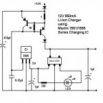
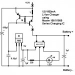
I also found other ways to use these chargers. I designed and made 2 so far using the 1555. I made them 12V since more it's easily found than 5V sources, and you can use them from a car battery or cig lighter.
The first charger uses a heatsinked-7805 from 12V to feed the Maxim 1555 the 5V power into the DC pin for about 250-280mA. It runs a bit warm. I have a LED on the CHG pin and it comes on when a battery is connected. It shuts off when fully charged! I've used it to charge my extra Li-Ion cells and it works good. However, I wanted more charge current for bigger 18650 cells.
The second charger has a 650mA output and also runs from 12V, and uses the 100mA USB lead of the Maxim 1555 +7805 to drive a PNP 650mA CCS. The Power PNP adds extra charging current for the battery, disspates the majority of the power, instead of the IC, and it follows the voltage of the IC chip, maxes out @ 4.18V. The Maxim chip runs much cooler using the 100mA input, so the chip doesn't run as hard and hot as normal use. The CCS only comes on if the Chip uses over 65mA, so when the battery is nearing full charge, the CCS shuts off, and it's being charged by only the Maxim IC at lower currents. I also used a LED for this charger, and it works as well. However, the 80W Power PNP gets HOT and I need to mount a suitable heatsink. If I get a good enough heatsink, I may mod it for more current 1-2A.
I love how these chips can run other circuits. It saves complexity, parts count, and is reliable to charge at the right voltage.
I used a IC-chip Circuit board for ease of use and mounting for both chargers.
I haven't yet used a chip for another flashlight yet, but I plan on making a small board for them.
Thanks Anonymous1 for the helpful tip on the Maxim chargers. Hopefully many DiyAudio members can benefit from this, esp since Li-Ion cells are hard to charge properly.
The Mini Maxim chargers are really good, they charge to a good voltage (4.16 avg, 4.19 open V) and charge the cell quickly.
I also found other ways to use these chargers. I designed and made 2 so far using the 1555. I made them 12V since more it's easily found than 5V sources, and you can use them from a car battery or cig lighter.
The first charger uses a heatsinked-7805 from 12V to feed the Maxim 1555 the 5V power into the DC pin for about 250-280mA. It runs a bit warm. I have a LED on the CHG pin and it comes on when a battery is connected. It shuts off when fully charged! I've used it to charge my extra Li-Ion cells and it works good. However, I wanted more charge current for bigger 18650 cells.
The second charger has a 650mA output and also runs from 12V, and uses the 100mA USB lead of the Maxim 1555 +7805 to drive a PNP 650mA CCS. The Power PNP adds extra charging current for the battery, disspates the majority of the power, instead of the IC, and it follows the voltage of the IC chip, maxes out @ 4.18V. The Maxim chip runs much cooler using the 100mA input, so the chip doesn't run as hard and hot as normal use. The CCS only comes on if the Chip uses over 65mA, so when the battery is nearing full charge, the CCS shuts off, and it's being charged by only the Maxim IC at lower currents. I also used a LED for this charger, and it works as well. However, the 80W Power PNP gets HOT
and I need to mount a suitable heatsink. If I get a good enough heatsink, I may mod it for more current 1-2A. I love how these chips can run other circuits. It saves complexity, parts count, and is reliable to charge at the right voltage.
I used a IC-chip Circuit board for ease of use and mounting for both chargers.
I haven't yet used a chip for another flashlight yet, but I plan on making a small board for them.
Thanks Anonymous1 for the helpful tip on the Maxim chargers. Hopefully many DiyAudio members can benefit from this, esp since Li-Ion cells are hard to charge properly.

- Status
- This old topic is closed. If you want to reopen this topic, contact a moderator using the "Report Post" button.
- Home
- Amplifiers
- Power Supplies
- Help with charging Li-ion cell