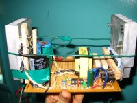
I finished building a simple 12V SMPS to test with and run amplifiers with. I've worked with SMPS before, but this is my 1st one I built. Although simple, I used big components to help reliability.
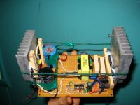
I used a computer PSU transformer from a dead 550W TTGI ATX Supply. I didn't have a decent toroid to use, so I used this instead to see how it would work, and it turned out well. I drive the 12V secondary coils in it with 12V and get my output from the mains side of it.
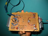
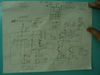
It uses TL594 @ 45khz in a socket driving hefty high-gain MJE15034/35 NPN/PNP Totem Pole Outputs to drive the MOSFETS. MOSFETS are NTY100N10 (123A) and output rectifiers are MUR3020 x 4 to make a bridge. (30A, 200V)
Rails depending on input voltage I've given it 11.5-15V gives me +/-35-50V rails. I haven't used it on a car battery at full power yet, but I've gotten over 150W with ease and no heat on a 14.4V NiCd battery. The MOSFETS stayed cool with NO heatsink with up to 100W, but work cool with the heatsinks at over 150W so far, and plan to test up to 300-400W.
Man, the post pic size is small. I have better larger pics too.
I used a computer PSU transformer from a dead 550W TTGI ATX Supply. I didn't have a decent toroid to use, so I used this instead to see how it would work, and it turned out well. I drive the 12V secondary coils in it with 12V and get my output from the mains side of it.
It uses TL594 @ 45khz in a socket driving hefty high-gain MJE15034/35 NPN/PNP Totem Pole Outputs to drive the MOSFETS. MOSFETS are NTY100N10 (123A) and output rectifiers are MUR3020 x 4 to make a bridge. (30A, 200V)
Rails depending on input voltage I've given it 11.5-15V gives me +/-35-50V rails. I haven't used it on a car battery at full power yet, but I've gotten over 150W with ease and no heat on a 14.4V NiCd battery. The MOSFETS stayed cool with NO heatsink with up to 100W, but work cool with the heatsinks at over 150W so far, and plan to test up to 300-400W.
Man, the post pic size is small.
I have better larger pics too.Attachments
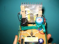
High speed diodes 30A 200V.
I used plastic marking tape (no adhesive) as insulators and greased both sides and put tight to heatsink to squeeze out excess heatsink grease. Same with MOSFETS but used blue tape.
I get that sticky HS grease all over my fingers that's why the heatsink looks covered, it really is a bunch of finger marks and extra grease for the most part.
Attachments
areza said:really liked it , care to share how u construct the transformer, how many turns, core size , shape, bmax , etc, thank you
Sure, Gladly
The transformer is stock. I did not modify it in any way.
The Transformer has 2 CT secondary outputs, one center tapped for +/- 5V and one same way for +/- 12V, other side for 120V mains voltage in, and had a clipped off lead for a center tap, I just soldered a #12 wire to the clipped lead to make it useable. Just use the transformer backwards and "drive" the 12V side, and get high voltage from the 120V side.
BTW, if you drive the 5v side instead with 12V you get real high voltage.
 I got +/-90V (180V) by doing this, so there's more uses still for this transformer (power inverter maybe)
It's a high-wattage computer PSU SMPS transformer (It's just slightly bigger than the transformers on 250-500W computer supplies of other kinds I've opened)
I'm still wondering how much this transformer is capable of. It does not get hot, it does have paralleled turns of wire, but not super thick.
I'm wondering if my semiconductors will hold up, how far I can really try to push it. My guess is the transformer will easily handle 300W but I'm hoping to try much more.
To get somewhat of an idea of what the transformer may handle, here's the ratings of the PSU it came from:
Original 550W TTGI Computer PSU ratings:
Input: 120/240VAC
10/5 Amps
Outputs:
5V 55A
3.3V 28A (comes from the 5V section of PSU)
12V 22A
Any of you have any ideas? I'm about to get a bunch of dead computer PSU to strip down and make easy SMPS with.
TheMG said:You should invest in some mica insulators, they're like $5 for 50, no joke.
Really...........where to get mica?
What I have also used with good performance is clear wide box (packing) tape, I stick the sticky side to the heatsink, and grease the semiconductor and put it tight against the non-stick side.
The problem with using tape, aside from the thermal performance, is if something ever goes wrong with the circuit that causes the mosfets or whatever other part to suddenly output a lot of heat, it might melt through the tape and short to the heatsink, likely resulting in (more) damage.
You can get the insulators off eBay, but most electronics suppliers will also have them. They are cheap, have good thermal conductivity, very low electrical conductivity (only a tiny bit of capacitance) and are resistant to high temperatures.
eBay item (example, there's more): 160200773161
Or from your favorite electronics part supplier, just search for "transistor insulator" or something similar.
luka said:Hi
BTW trafos primay is driven with ~160Vdc not 120Vac
True, but you get the idea
I like that the transformer was easy to mount to veroboard, and in general MUCH easier than using a toroid. IMO it looks better too.
I used such big MOSFET transistors because I'll use this as a test supply, and I expect it to get overloaded once in a while. For simplicity, I did not want to do parallels. That's why I used such overrated pieces. They seem to never get hot with a heatsink on them yet.
Those MOSFET are real brutes, I've shorted the supply, and put heavy loads on it and even got them hot with no heatsink, and they still work fine. However, I've already blown a set of 75N06s

Once I get better with SMPS, and find a few better transformers, I want to use 4 pairs of those NTY Mosfets to make a much larger 12V SMPS. I love the larger TO-264 case
Any recommendations on filtering? Or am I doing ok?
I used 50V 10000uf for each output rail with a 0.2uf cap across it, so I think the output has enough.
The input is inductorless, uses a 4700uf 16V cap, a 0.1uf/250V cap, and uses 12 gauge wires for power in. It seems to run fine with only 4700uf. In use, I was planning on using a large 60,000uf cap for it, connected to where the power enters the 12gauge wires for the PCB. I don't think the input inductor is necessary, but just another part to get hot, so I left it out.
I still have empty space left on the circuit board, so I may add some extra things.
place input cap as close as possible to fets, 2 x 4700uf may be enough, 60,000uf would cause some nice spark at the time u connect it to the battery, 10,000uf would overload fets and blow them up if soft start not used,
i m using 2 x 1000uf/25v with fets, and 110uf/400v after rectifier, hope this info would help.
i m using 2 x 1000uf/25v with fets, and 110uf/400v after rectifier, hope this info would help.
Hi
Use of smaller caps on primay side would be better for you, say 4x2200u, or something like that, even if you use 4x4700u ones, no seed to go above 15000uF for yout setup, and for output 2x1000uF will be way better then one 10000u, this is not 50/60Hz trafo, so you don't need that much capacitance, you will need to add snubber on primary and secondary side. so that it will work as it should
Use of smaller caps on primay side would be better for you, say 4x2200u, or something like that, even if you use 4x4700u ones, no seed to go above 15000uF for yout setup, and for output 2x1000uF will be way better then one 10000u, this is not 50/60Hz trafo, so you don't need that much capacitance, you will need to add snubber on primary and secondary side. so that it will work as it should
luka said:Hi
Use of smaller caps on primay side would be better for you, say 4x2200u, or something like that, even if you use 4x4700u ones, no need to go above 15000uF for your setup, and for output 2x1000uF will be way better then one 10000u, this is not 50/60Hz trafo, so you don't need that much capacitance, you will need to add snubber on primary and secondary side. so that it will work as it should
I mainly used the 2x 10000uf because they were available, and since I wanted to use it for audio, I wanted big caps for bass. The large MOSFETS have no problem starting up with them, despite the large current at start, so I'll keep them in the circuit. I do have 0.2uf caps also on output as snubbers.
I'm glad you let me know, that I can get by with a smaller capacitance say 2,200 uf or so on a future SMPS design. But I don't mind a bit of overkill for audio
Now my input 4700uf is as close as possible to where the 12
V high current enters the transformer. I was considering 10000uf, but if the 4700 is plenty, then it will stay. I still have that 60,000uf cap I can put across the power leads to feed the SMPS from, so I don't think smooth power will be any issue.
So it looks good so far.
I'm working on an amplifier also, so I can use this SMPS to power it during test, and also see how much audio output can be made from this SMPS
areza said:
i m using 2 x 1000uf/25v with fets, and 110uf/400v after rectifier, hope this info would help.
Thanks. That gives me a better idea as to what other cap values I can use.
I also used a 2200uf for the smps remote 12V input to power chip+totem poles. It's the green cap in the picture.
FWIW its much better to construct your OWN transformer for this... or else you will just be guessing the output current (for the xformer used)
I can see you used also CT for the output, your input is from +/-12 windings, and your output(160V windings) a CT too??
dont know they had that made...
I can see you used also CT for the output, your input is from +/-12 windings, and your output(160V windings) a CT too??
dont know they had that made...
RX5 said:I can see you used also CT for the output, your input is from +/-12 windings, and your output(160V windings) a CT too??
dont know they had that made...
In my original posts, the CT terminal was on the transformer primary, but the lead was clipped off, so I just soldered a thick wire on it to get access to it. In the original ATX PSU it didn't use the center tap.
I've noticed a few transformers are also like this, but not all, so you have to look for a possible center tap when selecting the transformer.
I imagine a non-CT one can still be used, with a voltage doubler to get the two rails.
Hi
Sure, but first it has to work, trust me having a lot of capacitance will be nothing good now that is now working right yet.I'm glad you let me know, that I can get by with a smaller capacitance say 2,200 uf or so on a future SMPS design. But I don't mind a bit of overkill for audio
So? Yes you maybe filter out some highh freq. signal that is comming from trafo (>1MHz). Base element of snubber is resistor, he does all the work, C is there only to stop lower freq. and DC, by that I mean I doesn't try to filter out main voltage, which would be impossible and from this you might see that snubber MUST be before rectifiers in other words right on primary and secondary side where windings come onto boardI do have 0.2uf caps also on output as snubbers
Capacitors aren't there to hold voltage high, like they would need with 50/60Hz transformers, they are there to provide peak current then transformer is switching... So it/ they have to have high current ripple more then capacitance. why? your battery is your power plant in this case, caps are there to provide the peak current.... Let say that current into amplifier is 100A which is a lot of watts, but current into trafo/trafos could be 150A at one part of switching cycle, which would mean that battery would have to provide this if there wouldn't be any caps. In other words, battery is to slow to react to this...that is why you have capsI was considering 10000uf, but if the 4700 is plenty, then it will stay
How much current ripple does it have? if not more then 4x smaller caps...I still have that 60,000uf cap
- Status
- This old topic is closed. If you want to reopen this topic, contact a moderator using the "Report Post" button.
- Home
- Amplifiers
- Power Supplies
- My New 12V SMPS w/Computer PSU Transformer