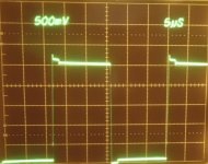
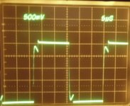
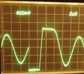
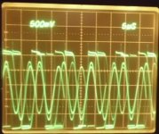
I have now rebuilt the smps prototype using epoxy glued EE cores from the scrapheap, the result is NO MORE FUNNY BEHAVIOUR!!! Guess simple 3F3 material should work nice since the EE cores are at least 20 years old 
The waveforms now keep relation between primary and secondary voltage. Efficiency for the veroboarded version is 82% at 1.29A/93V @ 14.5V input, and 85% eff given 9.9V input. I, havent dared to take any prolonged measurements using higher power levels as mosfets are expensive, and I am a coward when sober..
The current setup:
ee1.jpg
ee2.jpg
switchmodepower said:Nice. Do the waveshapes look better?
Do yourself a favor and when you wind the final version get a bobbin so you can wind carefully. Come back and I'll show you how to optimize the xfmr.
I will, I skipped the bobbin because it didnt fit the prototype
The waveforms have about the same amount of ringing, but the corresponcence between primary/secondary add up. I guess I have less leakage inductance as the lossless clamping-capacitors are way cooler than before.
Do you have any opinion regarding lossless clamping compared to simple RC clamps? I mean, are the lossless kinds more prone to ringing even when used on a real PCB? I have observed that if I go too low on capacitor ESR (I currently use 100uF/30mOhm electrolyte), things go really bad, high frequency ringing and very low efficiency etc, but it might just be the veroboard that cant keep up with the fast edges that X7R caps cause. I would prefer to use ceramic caps if I could as the ESR of electrolytes is an additional source of heat.
This is quite a difficult project. You will have trouble balancing the magnetic flux in the main transformer, resetting the current transformers (which may result in an erratic current reading) and operating at low duty cycles where current waveform synthesizing becomes more difficult due to turn-on spikes. You may consider a plain shunt at the drains instead, and peak current control.
Layout symmetry is critical for flux balancing, including resistance and leakage inductance of transformer windings. Toroids are easier because you can do bifilar winding.
Layout symmetry is critical for flux balancing, including resistance and leakage inductance of transformer windings. Toroids are easier because you can do bifilar winding.
Hi, I'm working in a push-pull SMPS to convert 12V to +-24V using the SG3525 PWM controler and two IRFZ44.
The transformer is made around a scrap toroid from a old audio car amplifier with 6+6 turns in the primary and 12+12 turns around the secundary.
When there's no load in secundary, the Vgs is a perfect square wave with almost 50% of Duty Cycle.

When I apply some load, the Vgs looks like this:

BUT when I modify the Duty Cycle, the Vgs looks very bad to me. Also is visible some resonance. (in facts,I'm using a 10ohm+2.2nF snubber).


How can I solve this problem?
Best regards,
Anthony
The transformer is made around a scrap toroid from a old audio car amplifier with 6+6 turns in the primary and 12+12 turns around the secundary.
When there's no load in secundary, the Vgs is a perfect square wave with almost 50% of Duty Cycle.

When I apply some load, the Vgs looks like this:

BUT when I modify the Duty Cycle, the Vgs looks very bad to me. Also is visible some resonance. (in facts,I'm using a 10ohm+2.2nF snubber).


How can I solve this problem?
Best regards,
Anthony
- Status
- This old topic is closed. If you want to reopen this topic, contact a moderator using the "Report Post" button.