I'm playing with a dual PSU for small signal applications - for something like preamps, with low current/clean supply needs. I found this article:
http://www.wenzel.com/documents/finesse.html
which shows a way to remove noise from simple regulated power supplies.
First off, I don't know if it actually works. Someone recently looked at it and thought it wouldn't. I have doubts too.
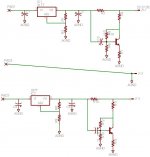
I've drawn up the schematic for a simple dual PSU using the clean-up circuit after 317/337 regs (component values are given in the above link). Anyone care to guess if it'll work or not? (especially the negative side, which I totally guessed on).
http://www.wenzel.com/documents/finesse.html
which shows a way to remove noise from simple regulated power supplies.
First off, I don't know if it actually works. Someone recently looked at it and thought it wouldn't. I have doubts too.
I've drawn up the schematic for a simple dual PSU using the clean-up circuit after 317/337 regs (component values are given in the above link). Anyone care to guess if it'll work or not? (especially the negative side, which I totally guessed on).
Attachments
Hi cuibono,
I didn't compare your schematic to the ones on the Wenzel site. But it has been reported that the Wenzel stuff does actually work.
But if you're using fixed-voltage three-terminal regulators, in a dual-rail power supply, you can greatly improve both line and load regulation by using an opamp to drive the reg's ground pin, with the reg's output AC-coupled to the opamp's neg input, and the opamp's pos input defining the actual ground rail. The opamp's power pins connect to the outputs of the two symmetric + and - voltage rails' regulators.
[Edit: I will also give details of component parasitics used during simulations, some of which were purely guesses, just in case someone wants to simulate it the same way:]
One of those that I simulated that seemed to work extremely well used [33uF (w/ESR 3 Ohms, ESL 9 nH, EPR 3Meg) || a 2.2uF film cap (ESR .005, ESL 2 nH] in series with [680 Ohms || 12 pF (ESR .023)], from the regulator output to the opamp's neg input, and 10k (Equiv Par Cap 0.3 pF) from opamp's output to neg input, with the opamp's output connected to [22 Ohms || 1000 pF (ESR .023)] in series with the regulator's ground pin (and no other connection to the regulator's gnd pin, & opamp pos output tied to ground rail in place of reg's gnd pin).
For that test, I had 100uF (w/ESR 1 Ohm, ESL 9 nH, EPR 1Meg) from the regulator output to the ground rail, plus 50 Ohms from reg out to gnd rail, plus a pulse current source pulling load current from reg output to the gnd rail (my 'active load simulator'), with current changing between 0.5A and 1.0A, with rise and fall times of 10 us, hold times of 100 us, and period of 200 us.
It worked incredibly well, actually; better than I could ever seem to get the Wenzel circuits to work. And I'm sure that my component values could be tweaked for better performance.
Residual disturbances in a 12V output voltage, from the 0.5A-to-1.0A current pulsing with 10us edge times, were about 2.3 mVp-p (after the output reached about 75% of its final level), compared to about 32 mVp-p without the opamp circuit.
Changing the load-current source to a sine wave, with a 1 Amp p-p amplitude and a 0.5 A DC offset (since I simulated only the positive supply rail), at 5 kHz, gave about 1.3 mVp-p of 5 kHz and around 50 uVp-p of 120 Hz in the output voltage, compared to about 19 mVp-p of 5kHz and about 730 uVp-p of 120 Hz without the opamp circuit. With the same setup, but a 20 kHz frequency, the 20 kHz component of the output voltage was about 2.5 mVp-p, compared to about 36.7 mVp-p without the opamp circuit. Faster opamps gave better performance.
Note that I simulated only the positive supply, and used a -12v ideal voltage source for the opamp's V- supply pin, and did not simulate with decoupling caps added for the opamp. The Max Timestep setting worked with about the same results from .00001 to .0000001. ALSO NOTE that NO wiring or PCB-trace parasitics were simulated.
I was using LTspice, so I used an LT1086-12 regulator, with 3X 2200uF (ESR 0.1 Ohm, ESL 9 nH, EPR 22k) || 0.1 uF (ESR .023, ESL 9n) on reg input, fed by a bridge rectifier made of four MBR2545CT Schottky diodes, which was fed by a sine voltage source with 12v*sqrt(2) 0-p amplitude and 0.25 Ohms series resistance.
Thanks Tom for your very thorough reply!
I built the positive half of the circuit I posted, and it reduced noise with a DC load. But I have been thoroughly cautioned by Jan Didden that it will not work with an AC load (like it would be in a preamp), so I am thinking of dropping it. I will test it with an AC load, but I bet Jan is right.
I'll guess using an opamp as with a three pin reg is the idea behind 'super regulators'? I love in-depth answers, but I'm just looking for something simple that would be better than just a three pin reg. I'll probably go for just the reg for now. The shunt circuit posted here look amazing, but maybe overkill for right now.
BTY, thanks for you circuit board etching instructions - I've used them for years now!
Just thinking more about this circuit - its not a lot to add on...
I've attached what I thought you were describing. Did I get it right? (my eagle app doesn't have a symbol for lm1086, so I used a 317 instead - are they swappable?)
A couple question:
The 50ohm resistor on the output, is it just to load the circuit? One wouldn't include it in an actual design?
The opamp should be as fast as possible?
How does one set the output voltage? Should I have included the standard adjust resistors on the 317?
Attachments
(I'd bet Jan is right, too.)
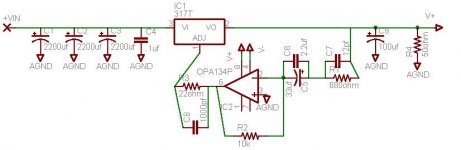
Here is a schematic that includes my three terminal regulator enhancement circuit:
I have only simulated it with a fixed 12V regulator, as shown. It should work with other fixed-voltage regulators, as long as the opamp can run from the voltages supplied.
It could probably be used somewhat-similarly with an adjustable regulator. But I have not yet tried it, that way.
I also have not tried it with dual voltage rails and two regulators, to check if there might be a startup problem with that configuration.
Passive components' values might need to be adjusted, for certain applications.
You can try other opamps. The LT1364 is just the last one I was testing with the LTspice simulator (free from linear.com). (The LT1364 might be a bit of an 'overkill', for this application, with its 1000V/us slew rate.)
Notes: Opamp power supply pins' decoupling capacitors are not shown. Optimal ground-returns' routing not shown. Protection diodes may be needed for certain regulator types, or for certain applications. See regulator datasheet.
Here is a schematic that includes my three terminal regulator enhancement circuit:
An externally hosted image should be here but it was not working when we last tested it.
I have only simulated it with a fixed 12V regulator, as shown. It should work with other fixed-voltage regulators, as long as the opamp can run from the voltages supplied.
It could probably be used somewhat-similarly with an adjustable regulator. But I have not yet tried it, that way.
I also have not tried it with dual voltage rails and two regulators, to check if there might be a startup problem with that configuration.
Passive components' values might need to be adjusted, for certain applications.
You can try other opamps. The LT1364 is just the last one I was testing with the LTspice simulator (free from linear.com). (The LT1364 might be a bit of an 'overkill', for this application, with its 1000V/us slew rate.)
Notes: Opamp power supply pins' decoupling capacitors are not shown. Optimal ground-returns' routing not shown. Protection diodes may be needed for certain regulator types, or for certain applications. See regulator datasheet.
Hi Tom,
I'm in the process of doing a dual supply, based on your schematic, and had a few practical questions. Assuming +/-15V rails, and a preamp drawing about 60mA, how much capacitance should I have before the regs? 3x4700uF seems high..
Similarly, what arrangement do you prefer for Vsupply pin decoupling? 10uF? smaller SMD bypass?
Any other opamp recommendations (considering price)?
Since we're designing for lower power in mind, would you change your diode recommendation?
I've got the schematic and layout almost ready, I'll post them soon.
Thanks again, Patrick
cuibono said:Hi Tom,
I'm in the process of doing a dual supply, based on your schematic, and had a few practical questions. Assuming +/-15V rails, and a preamp drawing about 60mA, how much capacitance should I have before the regs? 3x4700uF seems high..
Similarly, what arrangement do you prefer for Vsupply pin decoupling? 10uF? smaller SMD bypass?
Any other opamp recommendations (considering price)?
Since we're designing for lower power in mind, would you change your diode recommendation?
I've got the schematic and layout almost ready, I'll post them soon.
Thanks again, Patrick
For smoothing caps, I think that a lot of people like to use about 2200 uF per ampere, for the maximum peak current expected.
I'd probably start with 0.1uF X7R ceramic and 10 uF aluminum electrolytic for the supply pins. You could also add a third 0.1 uF, directly between the V+ and V- pins.
The opamps and diodes I showed were used mostly only because they were already available in the stock libraries included with LTspice. You can try the simulations with other ones, or just prototype it if you have a scope. All else being equal, a faster opamp, within reason, should work better, though. I would probably just use a single-component bridge for the rectification. For the 2.2uF, I'd probably use either polypropylene or polyester, depending on size limitations. The polyester box-type caps (e.g. AVX's BQ or BF series, IIRC, or similar ones by another manufacturer) would probably be the smallest 2.2uF through-hole film type you could find, if that's a consideration. Mouser.com has the AVX box caps.
First of all, the Wenzel idea is indeed working (I've tried) and it works better the more linear the correcting amplifier is (a single transistor isn't too good). A disadvantage is the increased DC/LF output impedance, one advantage is that it doesn't fiddle with the main regulators feedback loop, which brings us to Tom's ciruit.
While Tom's circuit is for sure worth a closer look and try, I feel somewhat unhappy with the additional loop gain from the opamp, it might get unstable under certain conditions (had that, too, with a related design where I sensed current high-side with a diff-amp and feed back the drop to the GND pin of a 7812).
Personally I prefer the last stage of a psu to be without feedback, a simple cap multiplier that is (and a duplicate in front of the reg, too), these tend to have way more bandwith that feedback'd approaches. And I use the LM3x7 in the lowest gain configuration, that is without the resistor divider, driving the adjust pin with a voltage (from a divider from the output) buffered with an emitter follower. This is essentially a stacking approach.. There is a post by the late Fred Dieckmann in one of the LM317 threads on this. IMO the main trick for a good regulation with LM317/78xx style regs is to load them and to have enough drop accross them -- same for the cap multipliers. The LM317 works really well with 50mA load and a 5V drop.
- Klaus
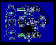
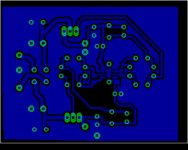
and here is the layout again, showing only tracks. There are actually very few ground connections...
I'm happy with it so far. It measures about 2" by 2.5". Some of the caps sizes may need to change, so layout might too. The board is designed to handle currents under 500mA, which should be plenty for preamps.
I'm happy with it so far. It measures about 2" by 2.5". Some of the caps sizes may need to change, so layout might too. The board is designed to handle currents under 500mA, which should be plenty for preamps.
Attachments
Cuibono,
In the sheet I see no connection for the opamp supplies, while in the board it seems to be connected to the reg's outputs, right?
One safety thing I would add: clamp diodes at the reg's REF (aka "GND") pins (say two antiparallel strings of a few 1N4148 each) to GND, to limit the range the output could ever swing.
Also, I would provide layout option to power the opamp from the inputs (divided down and filtered). And don't forget to load the regs with some 20mA at least (which could be partly had with opamps powered from the outputs and resistivily biased into class A).
@Tom: With which 12V reg model did you actually sim the circuit?
I assume a typical one, with a 1.2V internal reference and an integrated resistor divider, which would be 9:1 in this case. You amplify the noise with a factor of 14.7, so the internal Ref node would see a "overunity" feedback of the noise, a blip of -1mV at the output would give +1.5mV at the internal ref and a following 1.5mV increase of output, only to be damped / divided down by the (unreliable) dynamic output impedance of the reg and that of the output cap ESR.... this is what scares me a bit, looks like negative AC output impedance could happen -- did you do a output impedance sim? And, to start with, is it stable without output cap?
I think I need to sim it (also with various LM3x7 models I found)...
- Klaus
Hi Klaus,
I used the LT1086-12 model that is included with LTspice.
I just now tried simming the output impedance, using a current source from the output with 1A 'DC Value' ('bias' current, since supply is positive-only) plus 0.5A 'AC Amplitude', with an AC analysis run, plotting v(out0/i(out). It is about 412 mOhms at low frequencies and drops from that to about 254 mOhms while going from 10 Hz to 10 kHz. Without the output cap, it's only a little different, and only drops to about 342 mOhms, and does that between 10 Hz and 1 kHz.
Transient response still looks 'OK', without the output cap. But I haven't done any rigorous stability analysis.
I am sure that the circuit could be improved, in terms of both performance and stability. (But I have started a new job and don't have much time for anything else, right now.)
- Status
- This old topic is closed. If you want to reopen this topic, contact a moderator using the "Report Post" button.
- Home
- Amplifiers
- Power Supplies
- Help with dual PS noise shunt?