Hey!
I am making a regulated psu for some of my preamp projects and I would like to get a little feedback on the concept. I haven't designed the regulator myself - it is one of those that pops up multiple places on this forum with a possible origin in some old pass labs front ends.
I have attached the pcb layout and schematics with some random component values - being a generic psu, the values should be selected for the particular application. The layout also needs silk screen cleaning, but I'll do that later.
Attachment:
psu-reg.pdf
(too big for diyaudio)
Any tweeks I should make room for?
Conceptual explanation for newbies: (positive half from left)
- First some crc filtering
- Then a few mA's are taken through a jfet current source to supply the zener
- R6 and C20 is a low pass filter to reduce zener noise
- Finally Q2 and Q3 form a differential pair which regulates the voltage on Q4 to ensure that the point between R13 and R15 stays equal to the one provided by the zener.
I know the extra mosfets messes up the schem slightly, but they are there so one can switch between to220 or to247 devices. Most IRFxxx should work.
If there's any interest I might make boards available through a group buy. The board is rather large 15x10cm, because I wanted to make room for large snap in caps.
Hi,
can the LTP source sufficient current to drive the FET fast enough?
Don't build the regulator to mimic the ground rail.
Properly star ground the sections and then interconnect the separate stars at the output.
Have a look at GK's thread for more info.
Make sure the measuring bridge is built as a bridge and not the way shown in the schematic.
The resistance seen at the two inputs of the LTP is different, this may lead to more drift than if the resistances were matched.
Have you read W.Jung/J.Didden?
What is the worst case dissipation in the dropper FET? A single To220 should be sufficient here.
AndrewT said:Hi,
1. can the LTP source sufficient current to drive the FET fast enough?
2. Don't build the regulator to mimic the ground rail.
Properly star ground the sections and then interconnect the separate stars at the output.
3. Make sure the measuring bridge is built as a bridge and not the way shown in the schematic.
4. The resistance seen at the two inputs of the LTP is different, this may lead to more drift than if the resistances were matched.
5. Have you read W.Jung/J.Didden?
6. What is the worst case dissipation in the dropper FET? A single To220 should be sufficient here.
Thanks for your comments!
1. That depends on how much current that run through, but I expect this to be well within reach - the gate C on irf9610 is not that bad.
2. Are you taking about schem og layout. The green area is gnd plane.
3. What bridge?
4. Are you talking about thermal drift?
5. No
6. That depends on the application, but in most cases I think you're right. I just have so many irfp240 and irfp9240s and I know I'm not the only one...
")
Ah, the shunt reg Ever since I build the first shuntreg a couple years back, I have been wanting to power the entire play chain with shuntregs. The single best upgrade anyone can make, is to put a shuntreg into the preamp. A more open transparent and detailed soundstage is difficult to find. When I first put one in the NS10, it was wow..., where is the speakers.....? Everything else I have build and heard sounded dull, lifeless and compressed, in comparison.
Oh, and thanks for posting, if this turns into a GB you can count me in for at least 12 boards. With the added possibillity to use a TO247 device, it might be within reach to power my class-A headphoneamp also!
This opens great oppertunities, for the shunt fans
Ever since I build the first shuntreg a couple years back, I have been wanting to power the entire play chain with shuntregs. The single best upgrade anyone can make, is to put a shuntreg into the preamp. A more open transparent and detailed soundstage is difficult to find. When I first put one in the NS10, it was wow..., where is the speakers.....? Everything else I have build and heard sounded dull, lifeless and compressed, in comparison.Oh, and thanks for posting, if this turns into a GB you can count me in for at least 12 boards. With the added possibillity to use a TO247 device, it might be within reach to power my class-A headphoneamp also!
This opens great oppertunities, for the shunt fans
steenoe said:Ah, the shunt reg
Oh, and thanks for posting, if this turns into a GB you can count me in for at least 12 boards. With the added possibillity to use a TO247 device, it might be within reach to power my class-A headphoneamp also!
This opens great oppertunities, for the shunt fans
that reg isn't shunt , ya crazy danske .......
AndrewT said:
you should read Jung's regulator articles.
To see what a noted expert in the field has come up with.cviller said:
Why?
I have played a little this schem in the simulator. It is quite conventional and it seems fairly stable once the diff pair resistor values are dialed in. The concept is sorta the same, but with a shunt regulator instead of series.
sources need to be changed obviously...
sources need to be changed obviously...
Attachments
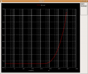
Here is a plot of the power supply rejection - when approaching 1mhz, the thing starts oscillating, but this can be prevented with some filtering, which I'll add later.
I got better low frequency rejection with opamps (higher gain), but the bandwidth was very limited compared to the diff pair (lm324 - I know cheap opamp). I think transistors will be better because it is easier to find good high voltage transistors for a reasonable price.
I got better low frequency rejection with opamps (higher gain), but the bandwidth was very limited compared to the diff pair (lm324 - I know cheap opamp). I think transistors will be better because it is easier to find good high voltage transistors for a reasonable price.
Attachments
It seems like it was, in fact a shuntreg Great.
Nice job. Once the design is entering the final stages, I can build a proto if needed.
Searching for shuntregs doesnt come up with much usefull projects.
BTW. Maybe you should change the threadname to something with shuntreg, for easier searching.
Great.Nice job. Once the design is entering the final stages, I can build a proto if needed.
Searching for shuntregs doesnt come up with much usefull projects.
BTW. Maybe you should change the threadname to something with shuntreg, for easier searching.
- Status
- This old topic is closed. If you want to reopen this topic, contact a moderator using the "Report Post" button.
- Home
- Amplifiers
- Power Supplies
- Multiple purpose dual regulated psu