Hi:
I did a Power Factor correction circuit using the on-line design utility from IRF.com.
I am using IR1150S chip and now my prototype is working, my goal is to obtain 1kw max. and for now I use a T130-26 toroid core stolen from a damaged PC smps for the boost inductor(too small) wound to obtain the required 270uH inductance.
As I did not find too much information about the type of toroid needed, I would like to know what kind of core material is better for this application, I am looking at 26 or 52 material types and maybe a T157 size would be OK.
Someone can give me advice on that?
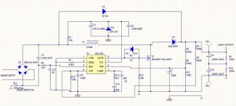
I enclose my actual schematic.
Thanks.")
I did a Power Factor correction circuit using the on-line design utility from IRF.com.
I am using IR1150S chip and now my prototype is working, my goal is to obtain 1kw max. and for now I use a T130-26 toroid core stolen from a damaged PC smps for the boost inductor(too small) wound to obtain the required 270uH inductance.
As I did not find too much information about the type of toroid needed, I would like to know what kind of core material is better for this application, I am looking at 26 or 52 material types and maybe a T157 size would be OK.
Someone can give me advice on that?
I enclose my actual schematic.
Thanks.
Attachments
Andy,
The inductor must be chosen so that it will not saturate at the maximum current it will be subjected to. The max current will set the 1/2 LI^2 (energy) capability of the inductor. The peak inductor current is pretty easy to calculate, but I don't have the formulas handy.
I would also recommend that the output caps be rated at a minimum of 250 volts, 300 would be better and 200 in unacceptable.
Rick
Consider either MPP toroids (see Arnold Magnetics and others), RF iron powder toroids (material 2 is the most popular, see www.micrometals.com ) or gapped ferrite and litz wire.
Use the search engine, there are some posts on this subject.
Use the search engine, there are some posts on this subject.
Actually, if the frequency is not too,high, Micrometals mix 18 is easier to work with, being 55 perm material. It's a good compromise between permeability (to keep the number of turns down) and low loss. Micrometals #2 is low loss, but the low perm will require you to lay down a lot of turns to get the required inductance. I've been using mix 18 E cores in my 1150 PFC, running at around 80 kHz.. They worked really well, but I replaced them with Cool-Mu/Sendust E-cores for higher efficiency (~ 1/2 point better). However, if you can't get Cool-Mu, Micrometals mix 18 is a nice second choice. Micrometals mix 26 is far too lossy to use for a PFC choke, though I guess you had to start with something....
Mix 52 is lower loss, but can have long-term degredation problems that take months to surface. A design that starts out cold melts down after running a few months. This problem appears to be confined to E cores, and may be a peculiar artifact of the way the flux turns the corners in the core, or it may also be the way the iron particles and binder distribute themselves when the core is pressed. A failed core when sectioned shows a distinct pattern of discoloration and deterioration at the corners. Mix 18 doesn't have the problem, and is lower loss.
I have also found that using an E core PFC choke resuts in a much cleaner leading edge current waveform due to the lower distributed capacitance in the winding. This is shown by both performance and actual impedance plots. My summary - Micrometals Mix 18, E cores.
I have also found that using an E core PFC choke resuts in a much cleaner leading edge current waveform due to the lower distributed capacitance in the winding. This is shown by both performance and actual impedance plots. My summary - Micrometals Mix 18, E cores. [/B]
Do you mean that E cores with single layer windings result in lower capacitance and higher self resonant frequency than single layer toroids? I have experienced the opposite.
Aren't stray fields stronger with iron powder E cores too? Then again, it's like taking a toroid and concentrating all the turns (and the RF losses) in 1/3 of the length of the core while leaving the other 2/3 unused.
I prefer toroids for inductors. If a single core requires too many turns or losses are too high, just stack more cores...
The E core I used was small (EI-375 size or EI-21 size) and the bobbin full. The toroid (T-130) had two layers of wire.It appears that the coupling effect of the toroidal core between all the inner turns may be a factor. The impedance plot for the toroid shows more capacitance and an additional high frequency resonance.
I fully realize that the concentrated turns on the E core result in more spray flux, but a shorted turn of foil around the outside of the core helps to tame this and also allows one to ground the core so that it doesn't act as an antenna. Just like anything else with switching power supplies, you take with one hand, and have to give a little something back with the other...
I'm currently optimizing EMI for my PFC, and I'm not seeing a lot of switching frequency harmonics show up like they would if the choke stray flux were coupling to the EMI filter. Actually, the 150kHz to ~4MHz EMI is shockingly well-mannered.
I preferred toroids, too, until I saw these results. Using an unsnubbed output diode, the leading edge current waveform went from intense underdamped ringing with the toroidal inductor to a clean, relatively small recovery spike (some of which may be capacitive) with just a small, small touch of damped ringing using the E core (something that could be cleaned up with a simple RC snubber). These results were obtained using the new Q-Speed diodes touted as SiC replacements. The ST PFC diodes are almost as good-looking, but the Q-Speed diode is more efficient. I'll be trying some new IR./Vishay diodes when I get the chance.
pfc inductor fflyback inductor
well
isn't this timely.
i have been fighting with my plasma emiting pfc. i have been using a ferrite. i guess i will change that
i found a huge problem with my other plasma emitting smp's when the current got too high. i had a bunch of so called iron powder toroids that are really ferrites.
so i cant wait to get back to the "lab" and try the mpp and iron toriods that my wife said had come.
so i hope this will solve my problems.
secondly what would be the best to use for flybacks ferrite or iron/mpp
?
i guess i didn't know what the cause and failure mode was supposed to be. an kept trying larger mosfets and dealing with crazy wave forms as the current started getting up...
thanks
IR1150S PFC
We use this chip in our professional amplifiers and it has serious turn on issues. We also use #18 cores from Micrometals which work well but DO NOT use a core which is too small. Our smallest size is a T175 and MMetals offer a T-200B which is a double stocked T200 core.
The problem with the IR1150S is that on turn on there is not enough dead time and the power device will blow. This is more apparant at 240v AC. We do not use a MOSFETS as IGBTs work so much better. I designed an extra circuit to deal with the PFC on turn on. The input surge issue is now a thing of the past.
IR are designing a new chip which they say will take care of the inrush current issue.
Steve Mantz
Zed Audio Corp.
Hi:
I am using a T157-2 iron powder toroidal by now, waiting for some CoolMu samples to try. It works great, but I had to use a lot of turns of wire to get 270uH on that core as it has very low AL.
Anyway, I did it using single wire to have room enough.
When the new cores come I will try with litz wire and simple wire to compare as I need less turns.
The big improvement on my prototype was the use of an hyperfast diode (8ETX06) on output. Now the PFC is feeding a half bridge SMPS to power one 1kw class D amplifier and the results are very good. Now the output voltage is very stable feeding the amplifier(before, the SMPS was not regulated by feedback and the use of the Pfc circuit is a great improvement regarding output voltage). Before the implementation of the PFC the SMPS output voltage had variations of 10 or 15 volts when the amplifier was near clipping but now the greatest variation I have is 4 or 6 volts (the output voltage is around +/-80 volts) without any feedback regulation as I use a quasi-resonant half bridge for the SMPS and it regulates itself in some way, enough for me as I want to use it for class D amps.
I did not notice any startup failure till now but I take note regarding the new chip from IR to replace the IR1150S
Re: pfc inductor
One or the other, isong one wire will have bigger I2R looses
jamesrnz said:ok,
with the pfc inductor should it be wound with multiple wire in parallel.
or can it be a solid wire like the out put inductor of an isolated smps?
One or the other, isong one wire will have bigger I2R looses
Re: IR1150S PFC
Wow, that's good to know considering I'm working on a design using that chip. Are you using the OVP pin (sleep mode) to accomplish this? Any additional drive requirements necessary for using IGBTs?
MOER said:We use this chip in our professional amplifiers and it has serious turn on issues. We also use #18 cores from Micrometals which work well but DO NOT use a core which is too small. Our smallest size is a T175 and MMetals offer a T-200B which is a double stocked T200 core.
The problem with the IR1150S is that on turn on there is not enough dead time and the power device will blow. This is more apparant at 240v AC. We do not use a MOSFETS as IGBTs work so much better. I designed an extra circuit to deal with the PFC on turn on. The input surge issue is now a thing of the past.
IR are designing a new chip which they say will take care of the inrush current issue.
Steve Mantz
Zed Audio Corp.
Wow, that's good to know considering I'm working on a design using that chip. Are you using the OVP pin (sleep mode) to accomplish this? Any additional drive requirements necessary for using IGBTs?
IR1150S
No we do not use the OVP pin. One of the issues whcih we have found is that one must not power up the PFC chip UNTIL the bulk capacitors are charged. Due to the fact that our amplifiers are used all over the world, the PFC must accommodate 85-265v AC and this presents some challenges on the start up procedure. The process we use is complex in that the tun on circuits must turn on each section of the power supply (PFC + half bridge + low voltage supplies) in the correct order and the surge limiter must also be switched out at the correct time. Another large issue is the resetting of the supply when AC power is applied. A test which contractors perform on our amplifiers is to turn the power switch off and then instantly turn it on again to see if they can blow up the supply. So I designed a reset circuit that forces the supply to start from zero each time AC power is applied and the it must go through the same turn on cycle each time.
The "Comp" pin is the port which controls dead time and this is the pin one must manipulete for dead time on turn on.
Also note that half bridge supplies are not happy having their PWM chips on and then B+ applied afterwards. They have a habit of blowing up.
IGBTs work far better than Mosfets in both the PFC and the half bridge, they are less expensive and the new generation of IGBTs from Fairchild and IXYS have hyper fast back diodes built in. The trick with IGBTs is to use higher value gate resistors for turn on as compared to that used for Mosfet drive. This reduces EMI substantially. At the output of the PFC right at the cathode of the PFC diode, use a high quality film capacitor to the common line = source of IGBT which reduces EMI as well. I also use a snubber from gate to emitter of the IGBT and this together with the other two "fixes" allowed us to get our amplifier through TEL testing.
Stephen Mantz
Zed Audio Corp.
Re: IR1150S
Stephen,
Many thanks for your thorough reply. Would you say that the low parts count using the IR1150s was not as advantageous as IR claimed or is this a common problem among many PFC controllers? I was also looking at the L4981 from ST...
MOER said:No we do not use the OVP pin. One of the issues whcih we have found is that one must not power up the PFC chip UNTIL the bulk capacitors are charged. Due to the fact that our amplifiers are used all over the world, the PFC must accommodate 85-265v AC and this presents some challenges on the start up procedure. The process we use is complex in that the tun on circuits must turn on each section of the power supply (PFC + half bridge + low voltage supplies) in the correct order and the surge limiter must also be switched out at the correct time. Another large issue is the resetting of the supply when AC power is applied. A test which contractors perform on our amplifiers is to turn the power switch off and then instantly turn it on again to see if they can blow up the supply. So I designed a reset circuit that forces the supply to start from zero each time AC power is applied and the it must go through the same turn on cycle each time.
The "Comp" pin is the port which controls dead time and this is the pin one must manipulete for dead time on turn on.
Also note that half bridge supplies are not happy having their PWM chips on and then B+ applied afterwards. They have a habit of blowing up.
IGBTs work far better than Mosfets in both the PFC and the half bridge, they are less expensive and the new generation of IGBTs from Fairchild and IXYS have hyper fast back diodes built in. The trick with IGBTs is to use higher value gate resistors for turn on as compared to that used for Mosfet drive. This reduces EMI substantially. At the output of the PFC right at the cathode of the PFC diode, use a high quality film capacitor to the common line = source of IGBT which reduces EMI as well. I also use a snubber from gate to emitter of the IGBT and this together with the other two "fixes" allowed us to get our amplifier through TEL testing.
Stephen Mantz
Zed Audio Corp.
Stephen,
Many thanks for your thorough reply. Would you say that the low parts count using the IR1150s was not as advantageous as IR claimed or is this a common problem among many PFC controllers? I was also looking at the L4981 from ST...
Eva said:Consider either MPP toroids (see Arnold Magnetics and others), RF iron powder toroids (material 2 is the most popular, see www.micrometals.com ) or gapped ferrite and litz wire.
Use the search engine, there are some posts on this subject.
EVA,
Would a T-200-26 work OK? I ask this only because I have a boat-load of #26 toroids lying around, different sizes, and would like to use what I have on hand. THX,
Steve
A #26 core would turn from white/yellow to brown/brown. They are more or less ok from 60Hz to about 25kHz. You see them these days in 60Hz differential inductors for EMI filters, and in coupled chokes for forwards, where they aren't supporting a whole lot of volt-seconds and have a fan blowing right on them. Type 52 has about the same perm with much lower loss, just don't try it in a PFC in E-core form (long-term degradation issues).
PFC
I have only had experience with the IR chip and some older Unitrode chips. They all suffer this problem. There are other chips from On-Semi, national etc and I see no provision for controlling the turn on of the main switching device when power is applied. Through trial and error and some blown IGBTs I figured out that massive dead time is required on turn on to protect the IGBT and reduce in rish current. However be aware that the turn on surge at 120v as compared to >200v is vastly different. You can get away with no surge supressor at 120v AC but NOT at >200v.
All we do is insert a simple 5 watt 620 ohm resistor in series with the positive leg of the bottom capacitor of the bulk pair (2 caps in series as we use a 1/2 bridge switcher). This resistor is bypassed with a relay once the supply is up and running.
I also keep the PFC disabled during the first 3 seconds of turn on. This allows the bulk caps to charge to some voltage (160 at 120v AC and 320 at 240v AC). Then I release the PFC and allow it to ramp up the main B+ to 385v.
#26 material is absolutely useless for the PFC coil. it has too much loss and the only two materials I recommend from Micrometals is #8 and #18. #8 is more expensive.
DO NOT skimp on the PFC coil because if it saturates then you are in trouble.
Stephen Mantz
Zed Audio Corp.
As previously mentioned, with 26 material you need to keep the volts*second product low in order to keep core temperature under control. This requires a large amount of turns that usually results in too high inductance (and capacitance) and too low saturation current. If you really want to use your 26 cores, you may try stacking 2, 3 or more of them and using a suitable number of turns so that losses are shared between the cores. Connecting several single-core inductors in series produces the same effect. If you manage to get core temperature under control, it would probably be reliable in the long term.
- Status
- This old topic is closed. If you want to reopen this topic, contact a moderator using the "Report Post" button.
- Home
- Amplifiers
- Power Supplies
- PFC inductor advice