What is SLB that you and Davenport refer to?
My impression of the SLB in the diagram I posted is what is referred to "ground break circuit". I assume Davenport is referring to the same thing.
However, realistically I'm planning to implement the system Nelson Pass uses in the F5T
Last edited:
Hi there,
I have gone quickly through this thread and tried some proposals, but sofar no succes.
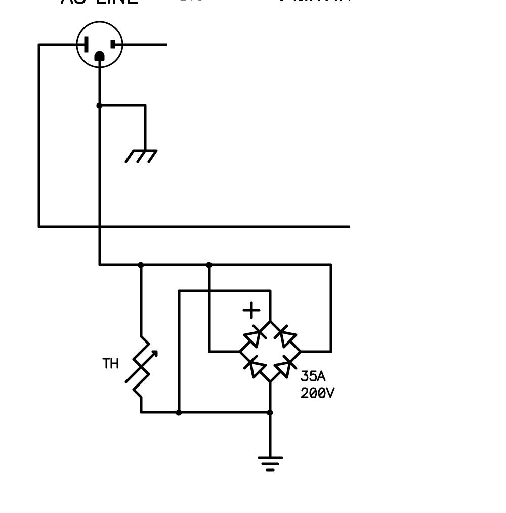
Please have a look at the wiring sheme below. What should I do to get rid of the hum?
Greetz
read posts 1 to 10.
in post 7 it is shown how to wire the input sockets, which must be isolated from the casework.
if this dont work, i would rewire your whole amp using a central star bolt, because in your picture and diagram this does not seem to be the case, connect up the ov's in order of the magnetude of the currents ie main tx ov, main caps ov, pa hi current ov, speaker ov, pa low current ov, input socket ov.
if you decide to rewire, consider to re-arrange the mains tx to be far from the pa pcbs, dont mount pcbs on the txmr.
good luck.


Interesting. I am currently fighting this ground hum. If I put a pair of amp (L+R) no hum. But once I put additional pair (to make it 4-channel) I hear hum.
At the end I had "all grounds connected everywhere" to obtain minimal hum - still audible on very quiet night.
What is the correct grounding for stereo amps then ?
it is all about current loops. You must understand where is the loop for particular signal and try to make it short as possible. All this STAR nonsense only confuses people. They are looking for "stars" , try this and that and at the end of the day connect it somehow just to get minimum noise =)
But, if you understand where high current loop goes, and low current loop goes, you can make them separate physically or placing coupling HF and LF capacitors =) But you have to look into the drawing.
Hi to all!!!
Here is my latest project and i have some questions.
An externally hosted image should be here but it was not working when we last tested it.
Do i need to separate signal ground on Lm3886 on second star ground?Or is just ok to have two star ground?
Nobody comment my post above.Is this mean that Layout is ok,Can i etch my board now?

In my case the "no response" means I don't understand.
I can't speak for other Members.
All black lines are grounding on top(component side) of board,red circles are capacitor positions.Right on picture are lm3886 amplifier circuit.
Question is do i need to separate signal gorunding line of lm3886 from MF,HF,speaker ground point and make a new route to the main star ground or to leave just the way it is?
An externally hosted image should be here but it was not working when we last tested it.
Thanks for replay!!!
Last edited:
I Had problems finding a isolated panel mount rca connector for my projects , But this really is a very most important thing.
I built a 5 channel surround amp with each channel in its own enclosure and one enclosure for my powersupply , so basically i have a small star ground in each of the 5 amplifier enclosures. Luckily i have now hum.
tang
In the past i have isolated rca from the chassis by using teflon plumbers doping tape. It is a very very thin white teflon ribbon that is used to wrap around threads in plumbing, but it is also electrically isolating and ive warpped it around threads of rca jacks to effectilvley isolate them from chassis.
I did that for my pearl 2.
Best is the neutrik rcas. They are isolated.
In the past i have isolated rca from the chassis by using teflon plumbers doping tape.
Can't understand why you needed to use teflon tape - every single RCA socket I've ever bought has come with a couple of washers made from teflon/nylon which isolate the RCA metal from the case metal?
The outer washer has a small circular ridge around the hole which locates the RCA socket into the middle of the drilled hole in the case, so that the RCA barrel is not touching the case. The inner washer simply isolates the nut from the case.
Regards,
Andy
For RF screening where should your shield connect.....
where the cable enters the unit, at the chassis, one way is to capacitively couple it. otherwise any noise picked up by the cable will be coupled into you electronics.
Yes, for a phono stage, the RCA socket ground lug should be connected to case earth - which, if it's mains powered, should be connected to IEC ground lug. Connection is with a 0.1uF ceramic.
Regards,
Andy
If you want rf shielding a small value capacitor at the entry point will provide a low impedance path for the RF whilst having little effect on the signal return. Where higher immunity equipment is required the IO has a completely separate input section with ferrite based pi filters to isolate the rf noise.
This is one of the main problems with single ended interconnect, there are always problems that can only be solved by compromise.
Henry Ott has some better info on this but I cant find the exact document at the moment (I am in sunny Harrow on site so don't have access to my home computer) It shows a variety of termination schemes and there effectiveness.
If I may simplify this, ground/earth loops are caused by multiple paths to earth, these paths have finite resistance and cause voltage/potential differences between the different earth points. Put a DVM between the earth points around your system and you will see varying voltages (both AC and DC). What you need is a SINGLE earth point for the whole system.
If you have hum problems try EARTH BUSTING the system. This means un-earthing all of the components except ONE, this can be your power amp. The Amplifier is then the ONLY path to earth. This is like star grounding the whole system.
DISCLAIMER you do need to careful with this approach as you are dealing with MAINS voltage. You need to meter each chassis back to the main system earth to check for continuity. If you disconnect the RCA leads from your preamp then you will also disconnect your mains earth.
RF is a little harder to ferrite helps as does good shielding of the enclosure. Short wave lengths bounce off metal. I use kitchen foil at work when measuring pico amps to shield the resistor, works quite well.
With RCA sockets try mounting them on acrylic panel before mounting in the amp, this will also reduce the capacitance.
Last edited:
I am presently battling this hum issue at my home. Its everywhere. So I bought all these audio loop ground loop filters like "The Stinger" or the "PAC SN-1 3.5" and the ubiquitous TOSlink optical cable. Yes, they stop a ground loop, but hey, if you listen real closely, there's still that hum in the background on your $2,500.00 amplifier. So you buy a Tripp-Lite Isobar. No joy. But at least it has a "protected" light.
!!!
OK, I go out to my power meter on the side of the house, and behold, some nut job has cut and removed my earth ground! The 10 gauge copper wire to the earth grounding rod is actually missing. I called my electrician and he is coming out on Monday to re-connect it. But in my phonecon with him he says the "electric company takes care of that". Seems like electricians only care about your light bulbs. But the bigger issue is the rotten transformer the "caring" electric company has out front along with its rotten ground wires coming down which have been spliced 5 times over in the past 60 years. Note to everyone - transformers in the yard radiate.
POINT -
So what I'm saying is that a star ground does not cure everything.
Proper grounding will cure all ground loop hum issues (hum can also be caused by faulty components or poor design). A ground loop is caused by resistance in the ground connection. This can be a few milliohms here and there, like a bad ground connection it all adds up and you will be able to measure a voltage between the grounds of 2 or more components. This is not a one size fits all, you will have to experiment to cure your hum issue.
I had a quick look at the stinger and it look to me to be a transformer. They will only remove common mode noise. If the hum is already in the signal these will not remove it.
If it is a power amp disconnect the preamp from power amp. If the hum disappears, then reconnect the preamp and remove all connections from the pre amp. Then install the one at a time. this will help isolate the problem to an area. If the hum is still there try shorting the inputs to power amp.
Dobar dan, I understand your question Or help me to see if I did.
You need another star ground, because physically you have one but the space is no handsome or practical?
I will read again the article of Davenport:http://www.diyaudio.com/forums/diyaudio-com-articles/163575-audio-component-grounding-interconnection.html" and/or you can gain time and together we can learn about.
I need to learn or remember.
The best regards
Last edited:
If you are really serious about learning about all this, buy borrow or rent this book, it is by one of the ultimate authorities on this subject, star grounds are a bit of an over simplification of a quite complex problem, that involves a whole frequency range of noise (the 50-60Hz being the easiest to detect).
Electromagnetic Compatibility Engineering - Henry W. Ott - Google Books
http://www.hottconsultants.com/pdf_files/aes-2007.pdf
Designing for Interference-free Audio System Components
A Practical Interference Free Audio System (Part 2)
Bonding Cable Shields at Both Ends to Reduce Noise
http://www.jensen-transformers.com/an/generic seminar.pdf
http://www.jensen-transformers.com/as/as032.pdf
- Home
- Amplifiers
- Power Supplies
- understanding star grounding