Hi,
I need a ±45V regulator, but I can't find any "simple" ways of doing it except by using LM317/LM337 HV parts. The problem is that I can't find these anywhere, even Mouser doesn't have them. Anyone knows how I could get 45V off the standard parts?
I found this:
http://www.national.com/ms/LB/LB-47.pdf
The regulator sees a 5V difference, but I don't know how which resistance I should give to R6 and if the circuit is possible to build for the LM337.
It's no problem at all, the voltage limit for 317/337 parts is the difference between input and output. You can use a standard 317/337 to regulate valve supplies if you like.
The key to long life is to protect the regs 'seeing' more than the 37-39v difference they are rated for, which is a risk at turn-on and switch-off. The diagram you link to does this, but an easier way is to 'clamp' the difference voltage. Add a 24v, 3w zener reverse-biased between the input and output pins of each regulator - which will avalanche first and save the regulator. It has no effect when the supply is up and running. You can then calculate the voltage set resistors as you would normally.
Yo must also include both the protection diodes shown in the LM117/317 datasheet, too.
DragonMaster said:I need a ±45V regulator, but I can't find any "simple" ways of doing it except by using LM317/LM337 HV parts. The problem is that I can't find these anywhere, even Mouser doesn't have them.
http://search.digikey.com/scripts/DkSearch/dksus.dll?Detail?name=LM317HVT-ND
DragonMaster said:
To build the Maida regulator from LB-47 would be outrageous overkill for a 45V supply. Personally, I would just use plain LM317 & LM337 and not sweat anything.
DragonMaster said:Thanks for the replies!
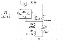
So this would work?
A few issues:
This would only work if your circuit has a significant draw. If you are feeding a few mA with this, the zener will supply the circuit needs and your regulator will be bypassed.
240 ohms is a little high for the out/adj resistor. National always uses 120 on their datasheets.
Why bother to add the input resistor?
If I was building this, I would just throw everything out except 2 resistors and the capacitor.
Yes, but using 240R cuts total dissipation in R2 and R3. The reg itself.really doesn't care what R1 is, it only sets a constant-current through the lower voltage-setting resistor(s).
Adding a smallish cap to ground after R0 will help no end. 0.1-10uF is enough, with R0 this will reduce noise feedthrough and keep input impedance low at the regulator - 317s like <10ohms source impedance.
BTW the ADJ pin averages 50uA leakage current, which x 8K4 means the reg a posted will deiver about [[(1.25/240) * (8K4)] + (50uA * 8k4) + 1.25v] , about 45.5V. Not way off target, but when using large-value voltage set resistors the ADJ pin current can be significant.
Adding 10uF across R2+R3 will significantly improve ripple rejection and lower the output impedance BTW.
martin clark said:The reg itself.really doesn't care what R1 is, it only sets a constant-current through the lower voltage-setting resistor(s).
That's not true. Read what AN-181 says about 5 mA being a typical programming current and 10 mA for commercial applications.
Interesting discussion...
Might I suggest something?
TL783CKC Digikey 296-10229-5-ND
Double check the part number... that might be a surface mount part.
about 69 cents... will take you up to 125 Volts...
")
http://focus.ti.com/lit/ds/symlink/tl783.pdf
Oh, and BTW, don't buy them from Joe's Cryo-special Speaker Cable and More. There was a bad batch a few years back. DigiKey will have good ones. Joe will have the bad ones.
Might I suggest something?
TL783CKC Digikey 296-10229-5-ND
Double check the part number... that might be a surface mount part.
about 69 cents... will take you up to 125 Volts...
http://focus.ti.com/lit/ds/symlink/tl783.pdf
Oh, and BTW, don't buy them from Joe's Cryo-special Speaker Cable and More. There was a bad batch a few years back. DigiKey will have good ones. Joe will have the bad ones.
240 ohms is a little high for the out/adj resistor. National always uses 120 on their datasheets.
I see 240 everywhere, they even recommend it IIRC ;-)
http://www.national.com/ds/LM/LM117.pdf
I bought them already...Why bother to add the input resistor?
This would only work if your circuit has a significant draw. If you are feeding a few mA with this, the zener will supply the circuit needs and your regulator will be bypassed.
!
What I want to do is to regulate the tube's voltage supply in the JLTi DIY gainclone. I got the amp working over 8 months ago, but there are loads of hum. The only time where the speaker output is hum free is during the few seconds when the amp is running on the capacitors after I switch the power off. I have to run the amp off a single transformer, unlike what the design recommends : one transformer for the tubes and one for the amp.
More filtering = less noise ? (I already bought the resistors, I have to use them somewhere...)Why bother to add the input resistor?
Oh, and BTW, don't buy them from Joe's Cryo-special Speaker Cable and More. There was a bad batch a few years back. DigiKey will have good ones. Joe will have the bad ones.
Most likely going to be a free sample if I use it anyways
Do you know if there's a negative voltage version?
DragonMaster said:What I want to do is to regulate the tube's voltage supply in the JLTi DIY gainclone. I got the amp working over 8 months ago, but there are loads of hum. The only time where the speaker output is hum free is during the few seconds when the amp is running on the capacitors after I switch the power off. I have to run the amp off a single transformer, unlike what the design recommends : one transformer for the tubes and one for the amp.
Whoa there. If you are ready to move onto tube PS regulation, have you already exhausted fixing the hum by troubleshooting the heater wiring and grounding scheme? Those are much more likely sources of hum in a tube circuit.
have you already exhausted fixing the hum by troubleshooting the heater wiring and grounding scheme? Those are much more likely sources of hum in a tube circuit.
I tried over 5 different grounding schemes, including different star grounding positions and grounding connected / disconnected to the chassis, without a single change in hum.
When I disconnect the tube and connect the inputs directly to the LM3886s, the output is pretty clean without a single bit of hum or buzz.
I also tried different things with the filament (It's powered from 6.3V DC using an LM317) like connecting one of the wires to the ground rather than leaving the regulator outputs floating (The 6.3V regulator is powered from a rectified 8VAC winding on the transformer), no differences here as well. I tried different RCA connectors insulated from the chassis, no difference. I think I just got the grounding scheme worse with all the experimentation, it started buzzing a bit when I don't use the tube with all the changes brought.
Note that there's no hum while the capacitors are discharging when I turn off the amp (but there's still sound), is this a good indication that it could be caused by the power lines?
Also, I tried a few different voltages(The amp has two 25-0-25 + 8VAC transformers with the 25-0-25 in series and the 8VACs in parallel to give 50-0-50 for the amp and tube and 8VAC for the tube filament PSU)
When the transformers were wired in parallel(About 25-0-25 before rectification), there was half the hum.
The only way I found to reduce the hum and keep higher voltage lines was to put different resistors between the 3886s and the tube, but I have less gain at the same time.
DragonMaster said:So far the only solution seems to be Martin's the TL783 doesn't have a negative voltage version. Actually, TI doesn't make adjustable negative voltage regulators. Will I have to get HV parts?
I have been running my LM317 non-HV with no protection diodes at all providing 160VDC for a tube preamp for a few years now. KISS.
DragonMaster said:So the datasheet's not all I should look at!
Not sure if that's sarcastic or not. Whatever you decide, at least consider adding an extra loading resistor to the schematic you drew. As I said, if you have a small small load, the current will just flow through the zener and bypass the regulator entirely. That is what will happen if you are just feeding a single tube with the regulator.
Guess what I just got, 10 years after using a soldering iron for the first time : A breadboard ! 
Now I'll be able to experiment w/o veroboard and point to point wiring betwen floating components. (i.e. Testing the new PSU.)
My old method was to make sure everything works before building anything. Then build, then find the errors if there are any, exactly what happened with my gainclone. I built the minimum circuits and now need to add tons of stuff.
Now I'll be able to experiment w/o veroboard and point to point wiring betwen floating components.
(i.e. Testing the new PSU.)My old method was to make sure everything works before building anything. Then build, then find the errors if there are any, exactly what happened with my gainclone. I built the minimum circuits and now need to add tons of stuff.
the input voltage size
the input voltage size?? about 45v?
Thanks for the replies!
So this would work?
the input voltage size?? about 45v?
±45v
hello ,I need a ±45V regulator,too.have you finished? can you give me a schematic diagram
Hi,
I need a ±45V regulator, but I can't find any "simple" ways of doing it except by using LM317/LM337 HV parts. The problem is that I can't find these anywhere, even Mouser doesn't have them. Anyone knows how I could get 45V off the standard parts?
I found this:
http://www.national.com/ms/LB/LB-47.pdf
The regulator sees a 5V difference, but I don't know how which resistance I should give to R6 and if the circuit is possible to build for the LM337.
hello ,I need a ±45V regulator,too.have you finished? can you give me a schematic diagram
- Status
- This old topic is closed. If you want to reopen this topic, contact a moderator using the "Report Post" button.
- Home
- Amplifiers
- Power Supplies
- Standard LM317, can get 50V?