12v -> 24v power supply
Hi all,
i've been looking for some nice T-class amps, but most of them need at least 24v to produce a bit of power")
I would like to put one in my car, and I think the 41hz's Amp9 is a good choice. (its supply goes from 12v to 27v)
now, I need a 20A@24V supply for it.
i've been looking on the web but I didn't find that much content.
Does somebody have some schematics ?
Any ideas on how to make one ?
Thanks!
Hi all,
i've been looking for some nice T-class amps, but most of them need at least 24v to produce a bit of power
I would like to put one in my car, and I think the 41hz's Amp9 is a good choice. (its supply goes from 12v to 27v)
now, I need a 20A@24V supply for it.
i've been looking on the web but I didn't find that much content.
Does somebody have some schematics ?
Any ideas on how to make one ?
Thanks!
This actually ends up being very simple if you don't need isolation. even if you need isolation its not too bad. Look up "push-pull" power supplies. In short, you can build a simple, and cheap voltage doubler with very high efficiency and low size by using a ferrite toroid, 4 quality MOSFETs, maybe a small inductor, and a low ESR output capacitor.
Snubbing components can be added as needed.
The ferrite is would with 2 high current windings in a 1:1 ratio.
The ferrite is also wound with 2 low current windings with a 1:1 ratio to each other, and arount a 2:3 to 3:3 ratio with the high current windings. going 1:1 is fine if the MOSFETs can handel a 15V Vgs,
This makes the power toroid easy to wind.
Connect the primaries as a normal push pull would be connected.
Now, at the drain terminal of each MOSFET, connect the other 2 mosfets' sources. Connect the additional FETs drains together (forming a diode bridge, but with FETS). The extra windings on the toroid are used to drive the gate of the FETs (add a small resistor in series, and a mid-sized on in parrallel with the gate to help with turnoff and ringing.
Use a tl494 for the FET driver on the push-pull FETS. when one FET turns on, it engages a primary of the transformer, placeing 12V across it. 12V appears across the other primary for 24V total. The "syncronous rectifier" FET turns on because 12V appears across its gate. a bit later, everything flips.
This design acheives high utilization of the semiconductors and the copper of the transformer, and presents only fully-on MOS devices in series with the high current.
Chris,
Trying to visualize this layout. If it's what I think, it's similar to N8XJK's 11V-to-13.8V booster ckt that appeared in a back issue of QST.
Or, it could be a slight variation of the 4-switch Buck-Boost topology (not to be confused with "Inverting"), where V(out) lies within the range of V(in-min) & V(in-max).
Anyway, It's definitely worth a closer look.
Steve
Hey, just found this thread - I want to do exactly the same thing, power a AMP9 in the car.
Would a boost circuit work? I'd need 24v at 10a really, I can't see me hitting 20a.
After reading here: http://en.wikipedia.org/wiki/Boost_converter
Is a boost circuit simply a switching semiconductor, a cap and an inductor?
I'm getting a but mixed up as to why you need a toroid with more than 1 winding you see.
FWIW, I've got about 3 or 4 old busted car amps, so I can easily use their toroid cores for my own use. I also have loads and loads of copper wire, I'm just not sure where to start as far as the circuit goes....
Also, with a boost circuit, would output voltage vary with input voltage? So when your battery drops in voltage, will the boost circuits output drop too? Is there any way to prevent this?
N-Channel:
consider a push-pull, but ONLY the primary side. when one fet is active, Vcc is applied across both coils (by transformer action). thus, just getting 2x voltage can be accomplished without secondaries!
Since this is LV, and efficiency is key, syncronous rectification should be done, which is the rest of the design. the extra windings are for the sync-fets
@MikeHunt79:
yes/no. boost is a terrible choice for beginners*, and other designs can provide voltage gain without being based on the boost topology. a transformer, for instance, can provide a gain with a buck-derived design, giving a gain of D*(Ns/Np).
now comes the question -- do I _need_ regulation? line/load regulation means that the output voltage of the power supply does not change much when the input voltage or the output current change.
for many amplifiers, the answer is, not really. and the lack of regulation makes the design simple.
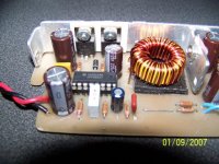
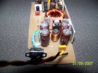
In general, you will see 1-2 toroids in the car amps -- 1 is a ferrite transformer, the other, when used, is an iron powder inductor. these are very different! The inductor is used in regulated designs. regulated designs also need feedback to work, which add complexity.
my suggestion is to use an unregulated push-pull design for your first attempt. these designs are highly efficient and simple.
the toroid with 4 two+ center-tapped windings is the push-pull transformer. basically, +12V attaches to the center. FETs switch each winding to ground, but alternating, and not at the same time. the other winding, but transformer action, sees Ns/Np times 12V, and using diodes, the correct secondary winding is attached to the correct output.
*boost and buck-boost have a bifurcation point giving two possible modes of operation with different dynamics. one of these modes introduces a right-plane zero requiring the controller bandwidth be reduced significantly. further, peak current mode control which is commonly used for highest line regulation is not unconditionally 1-cycle stable because there is not an isometic relationship between peak current and average current -- to acheive a high steady state duty ratio, the controller will send out a narrow pulse then a very long one, with the average duty ratio being correct!
consider a push-pull, but ONLY the primary side. when one fet is active, Vcc is applied across both coils (by transformer action). thus, just getting 2x voltage can be accomplished without secondaries!
Since this is LV, and efficiency is key, syncronous rectification should be done, which is the rest of the design. the extra windings are for the sync-fets
@MikeHunt79:
yes/no. boost is a terrible choice for beginners*, and other designs can provide voltage gain without being based on the boost topology. a transformer, for instance, can provide a gain with a buck-derived design, giving a gain of D*(Ns/Np).
now comes the question -- do I _need_ regulation? line/load regulation means that the output voltage of the power supply does not change much when the input voltage or the output current change.
for many amplifiers, the answer is, not really. and the lack of regulation makes the design simple.
In general, you will see 1-2 toroids in the car amps -- 1 is a ferrite transformer, the other, when used, is an iron powder inductor. these are very different! The inductor is used in regulated designs. regulated designs also need feedback to work, which add complexity.
my suggestion is to use an unregulated push-pull design for your first attempt. these designs are highly efficient and simple.
the toroid with 4 two+ center-tapped windings is the push-pull transformer. basically, +12V attaches to the center. FETs switch each winding to ground, but alternating, and not at the same time. the other winding, but transformer action, sees Ns/Np times 12V, and using diodes, the correct secondary winding is attached to the correct output.
*boost and buck-boost have a bifurcation point giving two possible modes of operation with different dynamics. one of these modes introduces a right-plane zero requiring the controller bandwidth be reduced significantly. further, peak current mode control which is commonly used for highest line regulation is not unconditionally 1-cycle stable because there is not an isometic relationship between peak current and average current -- to acheive a high steady state duty ratio, the controller will send out a narrow pulse then a very long one, with the average duty ratio being correct!
Might as well just use Schottky diodes. At 24v, the efficiency loss due to diode drop is very small.theChris said:This actually ends up being very simple if you don't need isolation. even if you need isolation its not too bad. Look up "push-pull" power supplies. In short, you can build a simple, and cheap voltage doubler with very high efficiency and low size by using a ferrite toroid, 4 quality MOSFETs, maybe a small inductor, and a low ESR output capacitor.
Snubbing components can be added as needed.
The ferrite is would with 2 high current windings in a 1:1 ratio.
The ferrite is also wound with 2 low current windings with a 1:1 ratio to each other, and arount a 2:3 to 3:3 ratio with the high current windings. going 1:1 is fine if the MOSFETs can handel a 15V Vgs,
This makes the power toroid easy to wind.
Connect the primaries as a normal push pull would be connected.
Now, at the drain terminal of each MOSFET, connect the other 2 mosfets' sources. Connect the additional FETs drains together (forming a diode bridge, but with FETS). The extra windings on the toroid are used to drive the gate of the FETs (add a small resistor in series, and a mid-sized on in parrallel with the gate to help with turnoff and ringing.
Use a tl494 for the FET driver on the push-pull FETS. when one FET turns on, it engages a primary of the transformer, placeing 12V across it. 12V appears across the other primary for 24V total. The "syncronous rectifier" FET turns on because 12V appears across its gate. a bit later, everything flips.
This design acheives high utilization of the semiconductors and the copper of the transformer, and presents only fully-on MOS devices in series with the high current.
Thanks for the info - I'll look into push-pull designs.
The only thing I am unsure of is how all the FET's and things work... If there a good introduction or sticky thread about push-pull?
I already know how full bridge rectification and bridge rectifiers work on normal mains amps.
The only thing I am unsure of is how all the FET's and things work... If there a good introduction or sticky thread about push-pull?
I already know how full bridge rectification and bridge rectifiers work on normal mains amps.
MikeHunt79 said:Thanks for the info - I'll look into push-pull designs.
The only thing I am unsure of is how all the FET's and things work... If there a good introduction or sticky thread about push-pull?
I already know how full bridge rectification and bridge rectifiers work on normal mains amps.
EDIT: Found this awesome link:
http://sound.westhost.com/project89.htm#fig9
I now know how push pull SMPS units work.
I looked on Wikipedia and found a link to this:
http://www.smps.com/Knowledge/Boost_PFC/Boost_PFC.shtml
Dear goodness those are some crazy equations!
http://www.smps.com/Knowledge/Boost_PFC/Boost_PFC.shtml
Dear goodness those are some crazy equations!
theChris said:N-Channel:
....consider a push-pull, but ONLY the primary side. when one fet is active, Vcc is applied across both coils (by transformer action). thus, just getting 2x voltage can be accomplished without secondaries!
Since this is LV, and efficiency is key, syncronous rectification should be done, which is the rest of the design. the extra windings are for the sync-fets.......
Chris,
If I understand you correctly, you propose a 2-F interleaved boost converter, with sync-FETs instead of Schottkys. I like this approach. Very interesting..... It's just like the 2-F boost I did, except I would replace the MBR2545CT with two low Rds(on) N-Ch MOSFETs (like an MTP75N06 or equiv.) and the appropriate gate windings. You have piqued my curiosity........

N-Channel said:
Chris,
If I understand you correctly, you propose a 2-F interleaved boost converter, with sync-FETs instead of Schottkys. I like this approach. Very interesting..... It's just like the 2-F boost I did, except I would replace the MBR2545CT with two low Rds(on) N-Ch MOSFETs (like an MTP75N06 or equiv.) and the appropriate gate windings. You have piqued my curiosity........
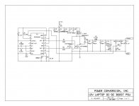
Envision a center tapped transformer without a secondary. Hold the center tap at +12V, ground one end and the other end will (theoretically) shoot up to +24V. If you just rectify this directly for your +24V, who needs a secondary winding?
If you need more than +24V (say, 36V) then you could add more windings to the primary in an autotransformer sort of fashion.
I did this trick in a DC/DC which boosted +5V to +15V. I used a secondary on this transformer for the (isolated) output, but used diodes to capture a 'double input voltage' off the primary which I used for +10V gate drive.
Hm. You'd be drawing quite a bit of DC current from your +12V source...Originally posted by gmarsh
Envision a center tapped transformer without a secondary. Hold the center tap at +12V, ground one end ...
2-F Boost?
is this the dual inductor bridge-like isolated boost? or an inductor in series with the push-pull? i've done the latter for isolated boost, but for the sync-fets to work you'd need to ensure CCM, or sense current in some manner.
gmarsh is correct -- my idea was that, with a conversion to 2x voltage, there seems no need to have a secondary.
N8XJK's (see QST NOV 2004) boost converter uses a secondary with c.t. tied to 12V. Mine uses no secondary. Here is the schematic. Chris- You propose swapping out the dual Schottky in place of two sync-FETs and appropriate gate drive windings, right?
Attachments
Oh, i got confused when you said "boost". I always associate "boost" with "boost-derived" regardless of any voltage gain/attenuation that might occur due to transformer action.
yes that is the design I was talking about, but with sync fets for added efficiency, as 1V of diode drop limits you to about 96% efficiency out of the gates.
not sure how well the syncfets would work. during deadtime the ON fet would attach the 24V supply to the 12V one through the transformer, and keep the sync-fet during the deadtime. Once the next main FET turns on, the supply is shorted until the syncfet is forced off.
hmm, there's probably a solution to all this though.
I'd say use a separate gate-drive winding for each sync-FET, along with the appropriate turn-off ckt to slam them off real hard, real fast. Limit the gate drive to, say, 12V. Reference the drives to their respective sync-FETs' sources, and you should be good-to-go. Just remember to get the phasing right so you don't turn the wrong switch-FET on with the wrong sync-FET. Ouch!
I was just saying you'd need a seperate gate drive transformer for the sync FETs that was seperate from the power transformer, as the load capacitance might hold the FETs on through the deadtime. basically, you have to find a way to ensure the syncFETs are forced off during the dead-time, and I'm worried that with one syncFET on, or with them floating, that either:
1.) the currently on syncfet would stay on, and the load would place voltage across the xfmr , which will keep that device's winding high. now there is no deadtime between switch and sync-fets and the switching device will short the load.
2.) the inductance will cause ringing, and will force a premature flip that may not give much deadtime between the time the switch begins turning off and the syncfet begins turning on.
maybe case 2 would be beneficial.
- Status
- This old topic is closed. If you want to reopen this topic, contact a moderator using the "Report Post" button.
- Home
- Amplifiers
- Power Supplies
- 12v -> 24v power supply