hy all of you. i've got some questions refered to a half bridge spms that i'm trying to build, and i've got a little problemm with the signal that goes in to the gate of the mosfet's.(the outpout of the transformer). the signal lookes like that(and i don't know how to improve it-i want to be perfect  ) :
) :
Some advices will be perfect. Thanks.
) :Some advices will be perfect. Thanks.
Attachments
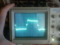
You can't expect perfectly square gate drive waveforms from a transformer. The bump after the leading edges is due to leakage inductance and is mostly harmless (as long as its amplitude stays controlled and symmetrical). The small peak after the trailing edges is also due to leakage inductance and it's not a problem as long as its amplitude (as seen from the opposite side winding) is not enough to turn on the opposire transistor.
Series RC networks in parallel with drive secondaries may help to tame peaks or ringing. Local turn-off buffers may also help (explained in other threads). Note that your waveform doesn't exhibit any ringing or lack of symmetry, so it looks quite good already (particularly in comparison with what other DIYers in trouble get). Are you suffering any reliability or efficiency problems?
Series RC networks in parallel with drive secondaries may help to tame peaks or ringing. Local turn-off buffers may also help (explained in other threads). Note that your waveform doesn't exhibit any ringing or lack of symmetry, so it looks quite good already (particularly in comparison with what other DIYers in trouble get). Are you suffering any reliability or efficiency problems?
i will find that in a couple of days, because the actual pair of irf740 that i've used 4 days ago are broken( because of me--i've used another transformer, with a strange wave-form) you can recomande me another good mosfet's? this is the circuit(power switches)...it's good?
you can recomande me another good mosfet's? this is the circuit(power switches)...it's good?Attachments
Two medium-power TO-220 SMPS switching MOSFETs that I have considered worth buying and that are currently in my parts box are:
FQP18N50V2
SPP20N60S5
Check datasheets and pricing if you are curious. Of course, there are at least one thousand alternatives, but if you are at the beginning of the learning curve it's better to blow the lower cost stuff...
FQP18N50V2
SPP20N60S5
Check datasheets and pricing if you are curious. Of course, there are at least one thousand alternatives, but if you are at the beginning of the learning curve it's better to blow the lower cost stuff...
That 'step' on the leading and trailing edge of the signal is due to the miller capacitance of the transistor when it turns on. To minimize the time-length of that (and hence switching losses), a lower impedance gate driver is necessary. Faster rise times will lead to more ringing and transients, though.
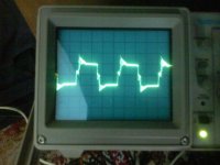
i'm back...again this is my new signal, when the smps is connected to a 70vcc transformer. i've measured the gate signals...and i have another problem. R3(100 ohm-2W) connected in series with C5(2.2nf),is a litle bit warm when it goes at 70 v, and became very hot, at 360vcc. what i'm suposed to do?
this is my new signal, when the smps is connected to a 70vcc transformer. i've measured the gate signals...and i have another problem. R3(100 ohm-2W) connected in series with C5(2.2nf),is a litle bit warm when it goes at 70 v, and became very hot, at 360vcc. what i'm suposed to do?Attachments
Snuber
Hi red_zone 003
The resistor-cap combination your are referencing is a snubber for the transformer primary and must be calculated for the switching frequency and transformer you are using. if you have a variac use it to adjust the bulk supply to about 20 volts or so then scope the network you will see a ringing signal on the edge of you primary pulse , then adjust the time base of the scope so that you can see the cycles of the ac ringing waveform clearly the measure the period and calculate the frequency, then calcualte the components for that frequency there are a few good methods on the net . Be careful around this network you can blow a scope and also hurt yourself always work at the lowest bulk supply necessary to visualize the problem, I use an old printer power supply 24 volts hey it works.
chas1
scope horz scale
If you have a scope of 100mhz BW you should be able to see the ringing and most scopes you can expand the horz. I have a old tek 600 analog scope. Also if you go to the URL below he explains this procedure in detail. Happy holidays.
Look for the paper on snubber compensation design. This should help you out . If the transformer is wound carefully you might only have to put a snubber across the primary. Make sure you use a good HiVoltage cap in series with the resistor.
chas1
http://www.ridleyengineering.com/index.html
- Status
- This old topic is closed. If you want to reopen this topic, contact a moderator using the "Report Post" button.
- Home
- Amplifiers
- Power Supplies
- help me with a half bridge smps(sg3525)