Hi,
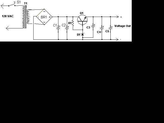
I’m busy building a 12v regulated power supply for my UPS
http://www.aaroncake.net/circuits/supply2.asp

What do u all think about this power supply, to me it looks cool.
I’ve tried a 6 volt version because I dint had the Zener for the 12 volt version, but it’s on the way
I'll need to draw 3 ~ 5 amps for 2 sec and then 1 amp all the way
thx
I’m busy building a 12v regulated power supply for my UPS
http://www.aaroncake.net/circuits/supply2.asp

What do u all think about this power supply, to me it looks cool.
I’ve tried a 6 volt version because I dint had the Zener for the 12 volt version, but it’s on the way
I'll need to draw 3 ~ 5 amps for 2 sec and then 1 amp all the way
thx
Hi,
this will work fine.
voltage will drop slightly as load current increases.
Beware,
the current rating of the transformer should be at least double the continuous output current. The original is risking overheating by saying output + 1A.
Check the temperature of the heatsink when operational. It may need to be very much bigger than you expect.
I used an old heat sink from an old amp to mount the transistor and used an indicator / brake light, 12v car bulb as load
And let it on for 1 ~ 2 min for a temp test on the transistor and it kind of started to get hot, but not hand burning hot, so if I must take a guess that the bulb draw 1.5+ amps because my other variable LM317T 1.5A power supply can only make the light burn for a couple of second before it starts to dim, I get a max of about 3.6 Amps on this regulator "Power Supply 6+v, with zener on base"
My transformer is kind of small but not tot small I have a smaller one also.
It’s a 28volt transformer and I get a 7 ~ 8Amps reading then I hook up my Amp meter onto a short, “I know it’s dangerous and stupid, but this way I can see the real power in a surge” I only do this with small transformers and not with my 28V which is rated 1500VA
Hi,
your 12V brake light bulb is probably drawing 1.7 to 1.8A.
Used as a continuous load then the transformer must br rated for 3.5A continuous.
To get 12V regulated you need at least 12Vac or maybe 14Vac to have sufficient drop across the regulator to work properly, particularly when mains voltage is low.
The voltage of the transformer is measured while it is delivering rated current into a resistor load.
That 14Vac & 3.5A means you need a 50VA transformer rating.
If you only need 1A continuous then 12Vac & 2A only requires 24VA rating.
When mains voltage is high the regulator dissipates more heat. You should design for both conditions, not for the happy mid-voltage range.
Don't try to use short circuit currents to estimate the capability of a transformer.
I’ve just located the rating on the specs,
Output: 24v ~ Max 28.8VA
Andrew T. can you please check out my other thread maybe you can also help out there, because nobody want to reply
12v UPS relays Trigger, 1 ~ 11v no trigger
http://www.diyaudio.com/forums/showthread.php?threadid=107468
Output: 24v ~ Max 28.8VA
Andrew T. can you please check out my other thread maybe you can also help out there, because nobody want to reply
12v UPS relays Trigger, 1 ~ 11v no trigger
http://www.diyaudio.com/forums/showthread.php?threadid=107468
theAnonymous1 said:Some noob questions:
What is the purpose of R1 and how do you figure what value should be used?
How many 2N3055 can a 1w zener drive?
Well I might say R1 is there to power the base on the NPN transistor and to get a reference voltage from the zener diode or something, my only fear is then the zener or transistor blows then I’m getting a full load of 24+ DC into my 12V line
Hi,
that other thread links to a site showing a crowbar.
Use it to short out the fused 24V supply when the output goes over voltage.
A 400mW Zener can just about do the job, if the correct supply voltage is fed to the correct resistor.
If you use too high an input voltage everything gets too hot.
Remember, design for the two limiting conditions:-
1.) low mains input voltage and
2.) high mains input voltage.
Yea, that crowbar circuit will work fine, I cant seem to locate that link, can you please supply me with it in a post, I've seem one with a zener and transistor once but cant remember where
EDIT: i finaly founded it
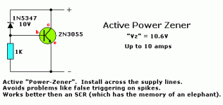
its called "Active Power Zener"
http://sound.westhost.com/appnotes/an007.htm
EDIT: i finaly founded it
its called "Active Power Zener"
http://sound.westhost.com/appnotes/an007.htm
An externally hosted image should be here but it was not working when we last tested it.
Attachments
AndrewT said:no, that is a negative version of your positive regulator.
It is a zener with a bit of muscle behind it.
It is called a "crowbar"
When it triggers it shorts the top to bottom of the triac.
That blows the fuse in the supply line, hopefully before anything is damaged.
No man, this device filter out all the voltages above the zener and short circuit it, and maybe that will be able to blow the fuse, I don’t want to use a triac, maybe I cant make it like with if the voltage get to high it flips a relay and disconnects the 28v DC from the rest of the system, this function can be useful for my UPS I’m busy building, I want a under power and over power disconnecter
The one you posted is a shunt regulator, if you go with that it will "double" regulate your line, theres still no protection and you have to heat sink the other transistor. A crowbar disables the supply in the event of overvoltage.
Check this site out: http://www.kbt-dc-supplies.com/crowbar.php
Check this site out: http://www.kbt-dc-supplies.com/crowbar.php
- Status
- This old topic is closed. If you want to reopen this topic, contact a moderator using the "Report Post" button.
- Home
- Amplifiers
- Power Supplies
- High Current Power Supply 12v, with zener on base
