Hi,
I’m busy with some UPS circuit and I need it to switch a couple of relays on then the power is back.
http://www.allaboutcircuits.com/vol_3/chpt_7/5.html

Can I replace the triac with a transistor because I don’t want to let the relays on until the power is down,
I basically want a easy method to trigger a couple of relays then the mains is back, currently I’m using a 10volt transformer on a 12v relay and if the mains drop the relay drop very fast, but the transformer is to small for 3 relays and then using 3 relays I hear a buzz sounds because it probably under power, in my circuit I have a regulated power supply and a small crap 10 – 11volt power supply just to do the relay work and the regulated power supply with huge caps is for the timer section and some other components
Purpose needed for:
1 ~ 11 volt - no trigger
12 volt - trigger
thx
I’m busy with some UPS circuit and I need it to switch a couple of relays on then the power is back.
http://www.allaboutcircuits.com/vol_3/chpt_7/5.html
Can I replace the triac with a transistor because I don’t want to let the relays on until the power is down,
I basically want a easy method to trigger a couple of relays then the mains is back, currently I’m using a 10volt transformer on a 12v relay and if the mains drop the relay drop very fast, but the transformer is to small for 3 relays and then using 3 relays I hear a buzz sounds because it probably under power, in my circuit I have a regulated power supply and a small crap 10 – 11volt power supply just to do the relay work and the regulated power supply with huge caps is for the timer section and some other components
Purpose needed for:
1 ~ 11 volt - no trigger
12 volt - trigger
thx
That circuit looks like a very complex diode, not what you need. What you neeed is a comparator, when the line is 1~11V the comparator does nothing, but when it hits 12V its output flips and enables or disables another circuit.
Here's a site with lots of comparator circuits: http://home.cogeco.ca/~rpaisley4/Comparators.html
An externally hosted image should be here but it was not working when we last tested it.
Here's a site with lots of comparator circuits: http://home.cogeco.ca/~rpaisley4/Comparators.html
Well, I don’t have any 250volt relays around me but it’s a good idea though, I only have 6v and 12v relays
I’ve found something on the net
http://www.electronic-circuits-diagrams.com/alarmsimages/alarmsckt2.shtml
In one of my circuits I use a gate, to make a yes a no; it’s in my timer function in my UPS
I have a couple of IC’s available that can be used for these purposes:
NE555
UA741
LM358
http://www.discovercircuits.com/DJ-Circuits/120vaclowvolt.htm
You’re Example:
I’ve found something on the net
http://www.electronic-circuits-diagrams.com/alarmsimages/alarmsckt2.shtml
An externally hosted image should be here but it was not working when we last tested it.
In one of my circuits I use a gate, to make a yes a no; it’s in my timer function in my UPS
I have a couple of IC’s available that can be used for these purposes:
NE555
UA741
LM358
http://www.discovercircuits.com/DJ-Circuits/120vaclowvolt.htm
An externally hosted image should be here but it was not working when we last tested it.
You’re Example:
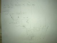
Ok what do you think of my design?
The above is the mains input and then a power failure or voltage error happens it switches off the supply to the main UPS part
How its works:
High voltage have a higher value resister, and if that led starts to glow then the voltage is wrong
Low voltage have a lower value resister and if that led goes out then the voltage is also wrong
Normal state is just a medium value resister that will work fine with most voltage variables and with a zener connected to cut over voltages
And that last section before its connects to the relay drivers, that’s 2 transistors, it needs to yes signals before the relays closes
No.1 will always be yes and the no.2 will also be yes, but if a voltage error happens then that gate before it will powered and then it will switch of the no.2 transistor
Normal state is only there to speed up the process incase of the caps powering the bases of certain transistors that might happens
Attachments
- Status
- This old topic is closed. If you want to reopen this topic, contact a moderator using the "Report Post" button.