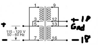
Could someone point out how to wire this transformer for 115V primary, 36V secondary with a center tap? I need +18V, GND, and -18V. The pinout info is at the bottom of page 2.
http://www.advancedcomponents.com/store/transformers/pdf/SSPF043.PDF
Thanks
http://www.advancedcomponents.com/store/transformers/pdf/SSPF043.PDF
Thanks
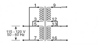
From the data sheet, you seem to have the primary right (3+5 live, 1+7 neutral) but not the secondary since they show a series connection as 12-16 connected (center), 9 / 13 outputs.
jake - you understand that the DC voltage will be 1.4 x AC voltage (full wave rectification, C-input filter) minus diode drops, right? A 2 x 18V AC transformer will get you about +/- 24V DC.
jake - you understand that the DC voltage will be 1.4 x AC voltage (full wave rectification, C-input filter) minus diode drops, right? A 2 x 18V AC transformer will get you about +/- 24V DC.
Yes I needed +/- 18V AC for this circuit: http://www.freeinfosociety.com/electronics/schemview.php?id=119 .
")

Hi,
if you accidentaly wire the primary windings out of phase the transformer will pull thousands of amps from the mains.
If you wire the secondaries out of phase the secondaries can appear as a short circuit and pull tens or maybe hundreds of amps from the mains.
Both of these problems cause serious risk to yourself and your transformer.
These risks can be eliminated by using a mains light bulb tester in the live mains feed. Build it and use it on EVERY mains powered project. And use it every time you modify a project.
Just take ACD's schematic and reverse one of the secondaries.
For double safety, the easiest and oldest procedure is to wire a high-wattage light bulb (good old filament type only!) in series with the primary when you first try to connect this to the mains, without the load. If the lamp lights up permanently, something is wrong.
For double safety, the easiest and oldest procedure is to wire a high-wattage light bulb (good old filament type only!) in series with the primary when you first try to connect this to the mains, without the load. If the lamp lights up permanently, something is wrong.
ACD - Sorry to have to say this but I think you *are* mistaken.
The data sheet is not a model of clarity - but it does show that for parallel primaries, you connect pin 1 to pin 7 to one side of the AC input; pin 3 to pin 5 to the other side of the AC input.
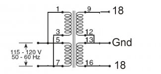
For a series connection of the secondaries, connect pin 12 to pin 16 to the center (ground), use pin 9 as the "upper" and pin 13 as the "lower" output (I won't use + and - lest someone confuse AC with DC here.)
This is a funny pinout, but at least the two circuits in the data sheet do agree with respect to winding phases (pin 1 same as pin 7, pin 9 same as pin 16), so presumably it is correct.
The data sheet is not a model of clarity - but it does show that for parallel primaries, you connect pin 1 to pin 7 to one side of the AC input; pin 3 to pin 5 to the other side of the AC input.
For a series connection of the secondaries, connect pin 12 to pin 16 to the center (ground), use pin 9 as the "upper" and pin 13 as the "lower" output (I won't use + and - lest someone confuse AC with DC here.)
This is a funny pinout, but at least the two circuits in the data sheet do agree with respect to winding phases (pin 1 same as pin 7, pin 9 same as pin 16), so presumably it is correct.
Hi,
read the last paragraph of post11.
If the terminal connections are wrong the bulb lights up and the secondary produces no voltage.
If the connections are correct the bulb might flash very briefly and go out. You can then measure the voltage on the secondary.
Either way no fuses blow, no explosions nor fires. Most of all no damage to the experimenter.
- Status
- This old topic is closed. If you want to reopen this topic, contact a moderator using the "Report Post" button.
- Home
- Amplifiers
- Power Supplies
- Help with phase/polarity of transformer