Eva said:Of course you can get 20dB lower impedance at 50Mhz (or at 500Mhz for that mather) but it is at the expense of 20dB higher impedance around 5Mhz... This is not an advantageous trade for audio because most amplifiers have its unity gain around this frequency and rail resonance will degrade phase margin. Every added capacitor produces a resonant peak. Measuring impedance at a single frequency tells very little information.
Note that I'm making my best effort to believe you because I have *never* seen dissimilar capacitors paralleled locally and directly in RF circuits like TV and radio tuners, though. Two or more dissimilar capacitors placed together and connected in parallel are only routinely seen in exotic audio equipment.
I just gave a single frequency as an example and I did actually mention the relevance of parallel resonances over a broad frequency range.
If you have never seen dissimilar capacitors paralleled locally in RF circuits then you honestly can not have looked at many - it is a standard RF design practice.
Would you like me to start posting up circuits?
Hi,
if we do ignore Eva's advice (at our circuit's peril) and parallel caps, then presumably we fit the smallest at the opamp/chip pins and fit the electroltytic somewhere down stream.
What is the significance of the trace length between these local and distant bypass caps?
Is there a recommended gap between them?
How much inductance and resistance is necessary to avoid resonant interaction?
What if we add a medium value film cap between the pin mounted ceramic and the distant electrolytic?
AndrewT said:Hi,
if we do ignore Eva's advice (at our circuit's peril) and parallel caps, then presumably we fit the smallest at the opamp/chip pins and fit the electroltytic somewhere down stream.
What is the significance of the trace length between these local and distant bypass caps?
Is there a recommended gap between them?
How much inductance and resistance is necessary to avoid resonant interaction?
What if we add a medium value film cap between the pin mounted ceramic and the distant electrolytic?
I'm logging off the net for the weekend now, but here are a few quick comments:
If you tried to bypass some fancy real high bandwidth audio opamps with electrolytic capacitors, you'd most likely have great deal of success at building an oscillator.
Don't just take my word for it, download the datasheet for just about any high performance opamp (audio or otherwise) and read the bypassing recommendations. 100nF at the supply pins are recommended virtually universally. This is not because 100nF caps are cheaper than 10uF electro’s, but because a low impedance supply bypass is required at rather high frequencies. If the supply leads are long, then parallel electrolytic capacitors are always recommended in addition. For really wide bandwidth opamps (especially video drivers, which require bypassing from nearly DC to 100+MHz), 10uF(or greater)+100nF+1nF might be the recommendation - but this is getting beyond audio.
Look up the bypassing recommendations for the 50MHz LM6161, for example – an IC which isn’t even that fast. The recommendation is 100nF in parallel with a 2.2-10uF tant.
Look up the bypassing recommendations of some audio power IC’s (say, 1W and up). You’ll find similar recommendations - but the electro’s in parallel with the recommended 100nF will be much larger.
Generally, when paralleling caps of different values it is generally necessary to keep the tracks between them as short as practicable to keep parallel resonances at bay.
Cheers,
Glen
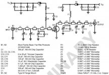
Oh, and here is a pic for eva (see MRF1517T1 datasheet):
Attachments
G.Kleinschmidt said:
Nearly anything over 100uF falls in a heap above a few tens of MHz, and degrade significantly quite a lot earlier.
I do a lot of mixed signal RF / audio stuff where stages are decoupled from each other with RC, LC (or combination) filtering of the supply rails, where it is necessary to decouple the rails for both audio frequencies and RF frequencies. A small 100nF MKT capacitor (for example) in parallel with a typical 100uF electrolytic can easily give a 20dB or more reduction in the impedance bypassing the rail to ground at 50MHz.
I also came to the conclusion that the large e-caps act inductive at higher frequencies, see my early posted measurements.
But these measurements also showed poor HF properties of MKT caps. How do you get good HF behavior from them?
The only thing during my measurements that showed good capacitor properties up to 110MHz was a SMD chip cap. Furtheron I found another very nice property in the X7R ceramic chips. Quite some HF losses resulting in nice damping of oscilations.
http://www.diyhifi.org/forums/viewtopic.php?f=22&t=1203&p=30452
I am becoming more&more a fan of X7R chip capacitiors!
Hi,
Thanks to all for the discussion so far. I'm trying to learn here.
I'm interested in SMD film caps.
I found this (commercial) info which compares dielectrics:
they state that MKT (PET-HT ) and MKI (PPS) perform better than NPO and X7R (and Tant for that matter) in several, IMHO, critical features, like ERS, dielectric absortion, aging, mode of failure, non-linear distortion (3rd harmonic)...
http://docs-europe.electrocomponents.com/webdocs/0066/0900766b80066c93.pdf
Who has info to contrast this statements?
Regards,
M
Would you, at least, agree that the common practice shown in this randomly chosen picture, which describes the particular way in which most audio related people understand the concept of "stiffening supply rails at high frequencies by paralleling capacitors" is completely useless?
Of course, if you stack two 0603 SMD chip capacitors under an electrolytic and near the load, you are leaving little room for resonance, but this is not what audio people does.
AndrewT:
If you connect capacitors in parallel, any wiring inductance between them will make resonance much worse. They must be paralleled together, like soldering a SMD chip ceramic to the legs of a thru-hole electrolytic. If you parallel them away from the IC, then wiring inductance cancels any improvement in HF supply impedance. If you parallel them near the IC, then you need a set of capacitors for each IC and you have to isolate each set from the others with inductors and/or resistors to prevent mutual resonance.
Figure out what happens when you have several small supply bypass capacitors randomly spread along a large PCB and all them are connected together in parallel through long tracks. This usually results in a system with several resonant modes and unexpectedly high HF supply impedance in the 100Khz to 10Mhz range. A system with less capacitors is likely to exhibit lower impedance in this frequency range.
An externally hosted image should be here but it was not working when we last tested it.
Of course, if you stack two 0603 SMD chip capacitors under an electrolytic and near the load, you are leaving little room for resonance, but this is not what audio people does.
AndrewT:
If you connect capacitors in parallel, any wiring inductance between them will make resonance much worse. They must be paralleled together, like soldering a SMD chip ceramic to the legs of a thru-hole electrolytic. If you parallel them away from the IC, then wiring inductance cancels any improvement in HF supply impedance. If you parallel them near the IC, then you need a set of capacitors for each IC and you have to isolate each set from the others with inductors and/or resistors to prevent mutual resonance.
Figure out what happens when you have several small supply bypass capacitors randomly spread along a large PCB and all them are connected together in parallel through long tracks. This usually results in a system with several resonant modes and unexpectedly high HF supply impedance in the 100Khz to 10Mhz range. A system with less capacitors is likely to exhibit lower impedance in this frequency range.
What if the electrolytic is large enough that it becomes resistive at the top of the audio band, and Cbypass is chosen to be small enough not to have significant reactance below that frequency, and what if at that frequency, the wiring to the circuit does not have significant inductance?Eva said:Would you, at least, agree that the common practice shown in this randomly chosen picture, which describes the particular way in which most audio related people understand the concept of "stiffening supply rails at high frequencies by paralleling capacitors" is completely useless?
Further bypasses at the circuit being optional and a separate question.
@Maxlorenz:
The key to your question is: '...perform better...'
Low ESR and especially low dissipation factor at high frequencies is not always desired. Low dissipation factor in HF is resulting in low damping of parasitic resonances.
What you rate good is always depending on the application. Normally I would rate a formula 1 race car to be the better car than the Chinese Landwind. But I you have to go on unpaved roads ... you know... the Landwind will make the race, no question. (BTW: Opposite from common thinking China has a lot of very good roads and they are pushing their infrastructure in an absolutely unbelievable way!)
Also your data sheet gives no information about the HF properties. No graphs about Z vs. f ....
Coming from the stacked construction I would guess that these SMD caps have fortunate high resonance frequencies, but having this specified (or measured on your own) would be a good idea if you want to use it HF filtering.
jnb said:
What if the electrolytic is large enough that it becomes resistive at the top of the audio band, and Cbypass is chosen to be small enough not to have significant reactance below that frequency, and what if at that frequency, the wiring to the circuit does not have significant inductance?
Further bypasses at the circuit being optional and a separate question.
In my measurements there was not a single e-cap, which I would call 'resistive above xxx'. They all went inductive at HF. Resistive Z I only found around the resonance frequency.
Nevertheless I was positively impressed about the behavior especially of the lower capacitance e-cap types for higher voltage...
What if we were to define a threshhold. e.g. that it is resistive +/- 45 degrees. This is how I understood Eva when, IIRC, she suggested that it never goes inductive.ChocoHolic said:They all went inductive at HF.

paralleled caps -- simulations
Somewhere in this(?) thread I found the formula for a inductance-cancelling capacitance which read C=L/R^2, R being the series resistance of the net. I could not confirm this formula but derived a slightly different one:
C=4*L/R^2
L is the sum of the wiring/trace inductance and the ESL of the first cap and anything ahead, just the inductive part of the impedance a network analyser would see if the paralleling cap were disconnected. R is the resistive part plus the ESR of the paralleling cap. That cap's inductance is not used in the equation, but shines up as the output inductance. If we tap R right in the middle we get a totally flat output impedance for that point (when ignoring the second ESL here for now, for clarity), if we tap it elsewhere we get some sort of shelving curve for the impedance, but without any peaks/dips. These start to show up as soon as we use a smaller C, bigger C lead to "dips" only. I plotted the derivative of the output impedance also, there the optimum C gives the smothest and flattes rate-of-change curve. This optimum C will get quite large when the ESLs are small, something to consider.
Referring to the attached pic, I set the lumped total ESR and ESL of the first cap plus wiring, source etc to 100mR and 100nH, while the second cap has a lowish 2nH ESL and 10mR of ESR. The second C was calculated as shown above with C=4*ESL/ESR^2, giving 33uF. These values are not necessarily practical and were chosen for illustrative purposes, I'm aware of that. To show the influence of any mismatch from that value, I stepped the C values from x10 to x10µ (lowering the value), in a 1--3.16--10 stepping. The bright red curve is for x1. If the C is bigger there is no problem here but when we decrease it we get strong impedance peaks and dips. The magnitude of the peaks rises with f^2, the Q also gets higher with f. Lowering inductances lowers the peaks, as a tendency.
The formula for C is quite sensitive to R as it is a quadratic term in the expression, also the ESRs are generally ill-defined, depend on temperature etc. So it's quite likely to have a strong mismatch sometimes. We can see we easily have impedance differences of three orders of magnitude. If we happen to have such a tens-of-ohms peak around the GBW of the amp we might be in trouble. Using no parallel cap is more inductive than paralleling but still the impedance is benign. Using the right cap for parelleling improves things, using the wrong one or at the wrong location makes it really bad. I simmed a more complex, real world example (3-pin LDO-reg, e-cap, parallel cap, wiring/trace inductance) and got very similar curves. I think that illustrates Eva's specific point very well.
- Klaus
Attachments
jnb said:
What if we were to define a threshhold. e.g. that it is resistive +/- 45 degrees. This is how I understood Eva when, IIRC, she suggested that it never goes inductive.
Well 45 deg is quite a wide range and from my perception already the point of 0 deg is unpleasant, because this 0 deg coming from L&C in resonance, only damped by ESR. Zero deg is looking nice on AC-sweep paper, but is acting ugly in transient analysis and real life.
Coming from posting #83 we can expect that large e-caps will cross 45 deg already in the audio frequency range. Furtheron you should not demand the proper rail for the audio frequency range only. Large amounts of HF can completey spoil the function and/or performance and/or stability of amplifiers etc.
And if you you look to high end demands, then people are not only discussing if the circuit is still working somehow, then they start to be concerned about the IM residuals of rail ringing and music signal....
I came to the conclusion that for rail cap applications losses the caps are nice in order to dampen the resonances. You cannot basically avoid such resonances (for this we have to transfer the geometrie into hyperspace, making the real world set up inductance free), so you have to make them low Q. In this regard e-caps and X7R (or worse ceramics...) and tantalum are fine. Low ESR I do only appreciate at low f, but not at the resonances.
ChocoHolic said:
I also came to the conclusion that the large e-caps act inductive at higher frequencies, see my early posted measurements.
But these measurements also showed poor HF properties of MKT caps. How do you get good HF behavior from them?
The only thing during my measurements that showed good capacitor properties up to 110MHz was a SMD chip cap. Furtheron I found another very nice property in the X7R ceramic chips. Quite some HF losses resulting in nice damping of oscilations.
http://www.diyhifi.org/forums/viewtopic.php?f=22&t=1203&p=30452
I am becoming more&more a fan of X7R chip capacitiors!
I just used the MKT as an example over the electrolytics - just to put down some figures for a comparison. The +20dB impedance reduction at 50MHz with a 100nF MKT in parallel with a 100uF electro was something I quickly measured on the bench (with the 100R resistor to make a LPF as described).
MKT's are generally fine for most analogue audio stuff.
Cheers,
Glen
gootee said:[First, a little recapping:]
Cornell Dubilier now has this great Java capacitor-modeling applet on-line:
----------------------------------------------------
http://www.cde.com/applets/CDEspiceApplet/aframe.htm
----------------------------------------------------
This free, on-line Java applet plots capacitance, ESR, and impedance, versus frequency, at several temperatures, for many of Cornell Dubilier's wet electrolytic capacitors (more series are being added, apparently), AND, with a mouse-click, AUTOMATICALLY GENERATES A TEMPERATURE- AND FREQUENCY-DEPENDENT SPICE MODEL for any particular capacitor that's been included by CDE.
These automatically-generated temperature-and-frequency-dependent electrolytic capacitor models work well in AC, DC, and transient analysis modes, in LTspice.
(Aside: Note that whenever I click on the "Impedance Modeler" link at the above CDE link, I always get "Object Not Found", at the top. But everything still works, if you wait for the applet to appear.)
-------------------------
[Now, a little new stuff, about using the models in LT-Spice:]
It appears that they always use the same schematic, for the capacitor model, which I derived from their netlists and posted in an earlier message, in this thread.
With LTspice, at least, you can also create a new re-usable "F-capacitor" symbol (with + lead as node 1 and - lead as node 2, in the .asy symbol file), insert it into a schematic, and then right-click on it and copy and paste the SUBCKT name from the CDE-applet-generated subckt text file into the VALUE field,
e.g. "CDE_WetAluminumElectrolyticCapacitorLV",
and cut and paste the PARAMS portion into the VALUE2 field,
e.g. "PARAMS: Cnom=4301.4u Ls=14.0n Rm=0.0048 Rspp=0.0368 Rtun=0.0055".
If you save the CDE-generated subckt model text file, with the entire PARAMS portion removed from the .SUBCKT line, and then use a .include Spice Directive (.op button) to include it in your schematic, you can then use multiple instances of your new F-capacitor symbol, for different capacitor values and types, just by right-clicking on the cap's symbol and putting the correct subckt name in the VALUE field and the applet-generated PARAM: statement in the VALUE2 field.
To be more clear: You should only need to save ONE copy of the generated spice model text subckt file, as long as you remove the PARAMS: portion of the SUBCKT line (i.e. Remove "PARAMS:" and everything after it, in the .SUBCKT line in the CDE-generated spice model text file, and then save the file with whatever name you want to use in the .include directive in your schematics. Apparently you can also change the actual .SUBCKT name to something shorter or more convenient, as well.)
Cautionary Note/Warning: For now, it APPEARS that the same schematic is used for all of the generated models for all of the CDE capacitor series/types. And although the SUBCKT names are different for some of the generated models, it appears that the only significant differences between any of the generated model files are in the PARAM: statement. However, I have not checked EVERY one of their capacitor types' models. And, even if they are all the same, for now, that may change, in the future. So users should be vigilant about making sure that any generated models do match the single saved SUBCKT text file, if they want to use this re-usable symbol method. (If CDE does later change the model, e.g. different models for different capacitor types or series, you might need to save one subckt text file for each .SUBCKT name they use.)
Also, make sure to read the notes in the generated model file about setting the TNOM temperature parameter. (See below.)
P.S. :
I forgot to mention that it might be a good idea to check the "Visible" box for the VALUE2 line that contains the PARAMS:
statement.
Also, in the CDE-generated model file, they mention setting a "TNOM" temperature parameter. I think that, for LTspice, it's simply the TEMP parameter. Stepping TEMP, with a spice directive such as ".step TEMP 50 100 25", or ".step TEMP list 50 75 100", does change the frequency response of the capacitor model, versus TEMP. (And setting a "TNOM" parameter apparently has no effect, unless I'm doing it in the wrong place or something.)
As an example, you can connect a simple current source across the capacitor, and right-click on it and set its AC value to 1. After plotting the voltage at the cap's + terminal with an AC Analysis spice run, you can right-click on the voltage's plot heading and change the expression to be the voltage divided by the current source's current, e.g. V(n001)/I(I1). Then you can left-click on the vertical scale and change it to "Linear", to see the impedance plotted in Ohms, versus frequency (with Omega symbols in the vertical scale values, at least if nothing else is plotted). Adding a ".step TEMP [low] [high] [increment]" or a ".step TEMP list temp1 temp2 ... tempn" spice directive should then give an impedance versus frequency plot for each temperature.
Enjoy!
Regards,
Tom Gootee
http://www.fullnet.com/~tomg/index.html
------------------
A SIMPLIFICATION:
------------------
Actually, you don't even have to create a new capacitor symbol:
Simply CTRL-Right-Click on a standard capacitor, in your LT-Spice schematic, and then paste into the Value and Value2 fields, per the above.
Also, change the Prefix field from C to X.
That's it!
- Tom Gootee
Eva said:Would you, at least, agree that the common practice shown in this randomly chosen picture, which describes the particular way in which most audio related people understand the concept of "stiffening supply rails at high frequencies by paralleling capacitors" is completely useless?
An externally hosted image should be here but it was not working when we last tested it.
Well, I have had good results with that type of bypassing. I would use a slightly bigger bypass cap, like 2.2 uF.
Modern electrolytics have very low esl, almost as low as plastic caps. In the simulations, obviously, bypassing doesn't show any improvement as the esl are usually swamped by trace inductances.
I figure that the good results come from better dielectric properties of the film cap, something that is not modelled in spice, I think.
In any case, my results are real and there is no way you can convince me with any spice simulation that says otherwise.
I have had similar experiences with non-inductive MKP caps with long leads, like 2 cm. Normally you would expect them to be pretty useless with those big inductors on the sides. But they work marvellously as supply bypasses (albeit clumsy and expensive).
Thanks,
Abo
Hi
I spent a lot of time measuring capacitors, real caps, NOT simulating...
..and I read this thread...
..and I agree with Eva (he's alway trying to explain the true world but I saw some who don't want to forget their audio-maniac strong beliefs - remember me Jocko, a serius loss for this forum - how can people without even a 'scope talk about electronics and debate about resonances?)
..and I read the entire -big- diyhifi.org thread that someone linked...
but some of you are too busy to read till the last messages, so I post again the link of my hard job.
http://www.audiofaidate.it/forum/uploaded/caps_tests.zip
I hope you'll enjoy it!
PS. vertical axis is 10dB\division, so each square from top means 10dB more attenuation.

- Status
- This old topic is closed. If you want to reopen this topic, contact a moderator using the "Report Post" button.
- Home
- Amplifiers
- Power Supplies
- paralleling film caps with electrolytic caps