We are trying to revive an old SMPS design, and I had a few fundamental questions regarding how to take the voltage feedback from the secondary while maintaining isolation.
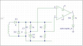
If you look at the picture included, the coil represents the isolated secondary of a transformer, and the secondary voltage is rectified to 150V. V1 is actually a 5V precision reference, and R2 and R3 are used to scale the secondary output voltage to compare to this voltage reference. After which, U1 (the triangle) drives the input of the optoisolator, which controls the primary side circuitry for feedback.
My question is this: should U1 be a comparator, or an opamp? I could see both working:
As a comparator, U1 would compare the scaled output voltage to the 5V reference, and then either turn the opto on or off if the output voltage is too low or too high, respectively.
As an amplifier, essentially the same comparison happens, but in a more "gradual" sense. The opto could be used in a more linear fashion (with its current transfer ratio) with an opamp is driving it as opposed to being used as an on-off switch.
Which one do you think would be more practical?
Attachments
- Status
- This old topic is closed. If you want to reopen this topic, contact a moderator using the "Report Post" button.