Hi, all!
I have a problem that I am unable to solve...
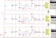
I have op-amp based voltage regulator:
Actually, I have three of them.
One for analog +5V, other for analog -5V and third for the digital +5V.
My power source are 3 SLA (12V) batteries. Each one for each VR.
If only analog +5V and -5V are connected everyhing is OK, but as soon as I connect digital and join DGND with AGND, analog +5V drops by half of the volt!
Is this a VR problem? Or gounding problem?
Any help is very appriciated...
Thanks,
Matej
I have a problem that I am unable to solve...
I have op-amp based voltage regulator:
An externally hosted image should be here but it was not working when we last tested it.
Actually, I have three of them.
One for analog +5V, other for analog -5V and third for the digital +5V.
My power source are 3 SLA (12V) batteries. Each one for each VR.
If only analog +5V and -5V are connected everyhing is OK, but as soon as I connect digital and join DGND with AGND, analog +5V drops by half of the volt!
Is this a VR problem? Or gounding problem?
Any help is very appriciated...
Thanks,
Matej
So are you saying you have 3x that circuit shown and they are only tied together at a single ground point? There is no other circuitry past the output?
I just took a cursory look, but it seems it should work. If you have something at the outputs, I would be suspicious about that part.
I just took a cursory look, but it seems it should work. If you have something at the outputs, I would be suspicious about that part.
aymanme said:So are you saying you have 3x that circuit shown and they are only tied together at a single ground point? There is no other circuitry past the output?
Well, the negative regulator is a little but different (diodes inverted, etc.). All the the same ground. Analog +5V and -5V are grounded already at the SLA battery. Digital +5V on the PCB (or at the battery - it does not change a thing).
Output circuit is AD1865N DAC for analog, and CS8414 receiver for digital.
I just took a cursory look, but it seems it should work. If you have something at the outputs, I would be suspicious about that part.
True, but we are talking about regulator. It should handle the load, right?
Matej
SY said:Separate opamps for each of the outputs (as opposed to duals or quads)?
I am using separate LF351N for each VR. Actually, all VRs are seperated circuit (they do not share anything) - expect the GND.
Matej
janneman said:Hmmm. That battery for -5V is grounded at it's pos terminal, right?
Jan Didden
Right. And I guess this is wrong?
Matej
SY said:That's what you want.
Do you have a scope? Sometimes when these puppies oscillate, a simple voltmeter reading shows a voltage change. It would be interesting to see what happens on the rails when the commons are joined.
Black Gates are being used.
I got the scope and I did not notice any oscillatation.
I have BG at the input and at the output. I also have a diode (reversed) to prevend wrong polarity connections. (Diodes can be tricky.)
But I noticed the following: if I connect +5V and -5V VRs everything is OK. Then I only have to connect AGND w/ DGND and this happens.
What happens is that that negative VR does not react - it's like before.
Positive VR changes... I noticed that op-amp outputs practically its max (near input voltage), and therefore opens the transistors.
Why?
I guess there is something in the orher digital VR? A diode? Caps?
Matej
Any chance you can post the whole circuit? Or at least a block of how your output circuit looks. You don't seem to have a complete circuit if you only connect the +/-5, you need a return path somewhere unless I misunderstand what you are saying. I still think this is probably something in your load circuit you are not considering.
To answer a previous question, yes it is still a regulator. But, on the systems we build, we spend way more time working on power and measurement issues than anything else.
To answer a previous question, yes it is still a regulator. But, on the systems we build, we spend way more time working on power and measurement issues than anything else.
Like has been said, these circuits can be unstable. You wrote neither simu nor scope did show a problem. That is strange, as I did a quick simu with quite comparable LF411 and BC547 parts and it heavily overshoots/oscillates somewhere between 10kHz and 100kHz depending on actual OpAmp bandwidth when output cap ESR falls below the 0.1R region...
KSTR said:Like has been said, these circuits can be unstable. You wrote neither simu nor scope did show a problem. That is strange, as I did a quick simu with quite comparable LF411 and BC547 parts and it heavily overshoots/oscillates somewhere between 10kHz and 100kHz depending on actual OpAmp bandwidth when output cap ESR falls below the 0.1R region...
It seems that I missed something in my simulation.
How did you similate? Can you send me the simulation file?
This would helped me a lot.
Thanks,
Matej
juergenk said:I think you wired them wrong.
And you are violating the common-mode restrictions of the LF351.
regards
I noticed my VR schema is a little bit different, but it is a standard one (a voltage divider to the op-amp input).
Can you be more precise about the common-mode restrictions you noticed... this might be it, since op-amp goes high.
Matej
juergenk said:the input voltage must have a certain distance to the rails, only inside this common mode range an opamp works, as it is intended
regards
I measured V+ and V- on op-amps and I got: 1.76V (V+) and 1.49 - 1.76V (V-).
This is all << Vin.
Matej
- Status
- This old topic is closed. If you want to reopen this topic, contact a moderator using the "Report Post" button.
- Home
- Amplifiers
- Power Supplies
- Tricky op-amp based VR problem