HI,
I need to include a Hi Side switch be used to turn on or turn off power to a Full H-Bridge. The Hi Side switch will consist of several parallel Mosfets that will remain continuously on virtually indefinately. This will rule out the use of bootstraping or transformer driven gate drivers since there is no practical way to refresh the gate voltage if the Mosfets aren't constantly switching.
To address this I was thinking of creating a floating supply using a small push-pull PS. The floating supply should be able to maintain a steading floating voltage to keep the mosfet turned on indefinately.
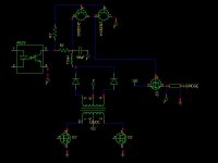
Besides creating my own with a Oscillator + Opticoupler + Gate driver Totem Pole Transistor pair, Is there an off-the-shelf device that does this? I am looking for methods to keep the part count to a minimum and to minimize PCB real Estate. Below is a simply schematic of a floating supply used to drive a High-Side Switch.
Thanks
I need to include a Hi Side switch be used to turn on or turn off power to a Full H-Bridge. The Hi Side switch will consist of several parallel Mosfets that will remain continuously on virtually indefinately. This will rule out the use of bootstraping or transformer driven gate drivers since there is no practical way to refresh the gate voltage if the Mosfets aren't constantly switching.
To address this I was thinking of creating a floating supply using a small push-pull PS. The floating supply should be able to maintain a steading floating voltage to keep the mosfet turned on indefinately.
Besides creating my own with a Oscillator + Opticoupler + Gate driver Totem Pole Transistor pair, Is there an off-the-shelf device that does this? I am looking for methods to keep the part count to a minimum and to minimize PCB real Estate. Below is a simply schematic of a floating supply used to drive a High-Side Switch.
Thanks
Attachments
How about a standard bootstrapped high side driver IC powered with a charge pump? You can drive the charge pump with the own oscillator of the system through a buffer, or with a separate 555. Note that most IRxxxx high side driver ICs don't require more than 0.5mA for steady state operation, so the capacitor values involved are going to be very small.
On the other hand, you can use a high and low side gate driver IC and employ the low side section as a buffer to drive the charge pump to power the high side.
Note that you can even drive the charge pump from the own switching nodes of the H-bridge if they are continuously oscillating.
On the other hand, you can use a high and low side gate driver IC and employ the low side section as a buffer to drive the charge pump to power the high side.
Note that you can even drive the charge pump from the own switching nodes of the H-bridge if they are continuously oscillating.
How about a standard bootstrapped high side driver IC powered with a charge pump? You can drive the charge pump with the own oscillator of the system through a buffer, or with a separate 555. Note that most IRxxxx high side driver ICs don't require more than 0.5mA for steady state operation, so the capacitor values involved are going to be very small.
Ok, I found IRF's AN-978 which basically uses a 555 Timer to pump charge the Bootstrap cap of a high side driver. I noticed that the gate drive output creates high frequency output dumped into a cap. Should I be concerned with generating noise?
http://www.irf.com/technical-info/appnotes/an-978.pdf
(see Page 18, Figure 17 - Ripple on Bootstrap Cap Voltage)
I think when I drive power through the H-Bridge, the ripple will be worse because the load is dynamic. This might create instability between the High Side MOSFET Switch and the H-Bridge. I think this problem can be addressed by adding some output caps and an inductor between the High Side switch and the H-Bridge to smooth out the load. Although this increases the part count and PCB real estate. Perhaps I can get away with a larger bootstrap cap and a small inductor in series?
FWIW: I found these high-dide drivers with integrated an pump charge (LM9061, LTC1156, LTC1161,MAX1614,MIC5011), but these all appear to be limited to voltages (Max ~26V) below my requirements. Alternatively I think N-Channel ORing Controllers such as the ISL6144 (up to 75V) might work with higher input voltages. Another Option I just though might be worth investigating are hot swap controllers.
Thanks Again
I have made this
http://www.diyaudio.com/forums/showthread.php?s=&threadid=99796
It enables full duty cycle 0-100% continuously not time limit as with bootstrap caps are having. Its simple and very basic than chargepump. Though I have replaced the EF bipolar with IRF840 Mosfet.
http://www.diyaudio.com/forums/showthread.php?s=&threadid=99796
It enables full duty cycle 0-100% continuously not time limit as with bootstrap caps are having. Its simple and very basic than chargepump. Though I have replaced the EF bipolar with IRF840 Mosfet.
I have made this
http://www.diyaudio.com/forums/show...&threadid=99796
It enables full duty cycle 0-100% continuously not time limit as with bootstrap caps are having. Its simple and very basic than chargepump. Though I have replaced the EF bipolar with IRF840 Mosfet.
Thanks, but in order to use this you need to have a voltage source 10+ Volts above the High side drain voltage. This is the same as using a floating supply.
I am thinking of using a Push-Pull controller such as the IR2085 or UCC3808 coupled with a opticoupler gate driver FOD3180. I think I'll have less issues using a floating gate driver instead of a charge pump. The only issue I've run into, is finding small transformer that is configured for push-pull. I may end up having to winding my own.
TechGuy said:HI,
I need to include a Hi Side switch be used to turn on or turn off power to a Full H-Bridge. The Hi Side switch will consist of several parallel Mosfets that will remain continuously on virtually indefinately. This will rule out the use of bootstraping or transformer driven gate drivers since there is no practical way to refresh the gate voltage if the Mosfets aren't constantly switching.
To address this I was thinking of creating a floating supply using a small push-pull PS. The floating supply should be able to maintain a steading floating voltage to keep the mosfet turned on indefinately.........
Thanks
Techguy,
What is the rail voltage? 12V? 24V? Higher? If it's say, 24V, then you can simply use a really BIG P-Channel MOSFET, like the Harris RFG60P05E, with an Rds(on) of only 26milliohms! Paralleling enough of them would eliminate the Rds(on) issues.
If this is hi-voltage (120-370VDC), then can you use alot of 500V-rated P-channels in parallel? Using the P-Channel devices eliminates the need for a bootstrapped supply because you simple pull the Gate 15-20V below its drain to fully turn it on. Just a thought................
how about a 555 through a couple of capacitors to a bridge of 1n4148's with the positive on the drain an the negative on the gate. n-channel fet of course. no relation to steve.... well maybe.....
provides both signal and ground isolation with minimal if any leakage
i use this with a 50 amp switch.....
i will look for the schematic.....
provides both signal and ground isolation with minimal if any leakage
i use this with a 50 amp switch.....
i will look for the schematic.....
How many ampere and volt? How fast?
Infineon has lot's of good stuff in that department. BTS660 handles 90 A, 58 V. Pretty nice
http://www.infineon.com/upload/Document/cmc_upload/documents/008/694/BTS660P_20030925.pdf
Infineon has lot's of good stuff in that department. BTS660 handles 90 A, 58 V. Pretty nice
http://www.infineon.com/upload/Document/cmc_upload/documents/008/694/BTS660P_20030925.pdf
What is the rail voltage? 12V? 24V? Higher? If it's say, 24V, then you can simply use a really BIG P-Channel MOSFET, like the Harris RFG60P05E, with an Rds(on) of only 26milliohms! Paralleling enough of them would eliminate the Rds(on) issues.
I will be running from 36V to 48V. I am avoid using P-Channel devices, while I could stack a bunch of them, it would increase the real estate required.
how about a 555 through a couple of capacitors to a bridge of 1n4148's with the positive on the drain an the negative on the gate. n-channel fet of course. no relation to steve.... well maybe.....
I thought about that, but the load will be an h-bridge. I am concerned about driving pump charge off the load might create some issues from all of the switching noise. I think my best bet is to use an isolated floating voltage source, and there really isn't much a of a difference in part count or PCB real estate.
How many ampere and volt? How fast?
Infineon has lot's of good stuff in that department. BTS660 handles 90 A, 58 V. Pretty nice
About 50A peak, 48V to 36V, very slow (turned on during startup, turned off during power down, or overload). That BTS660 does seem like a nice solution. Although I've already order parts to prototype a floating voltage driver. If I run into some issues, I'll try out the BTS660. Thanks for the suggestion!
Eva said:Why can't you just disable the full bridge? I don't think that an additional switch is required..........
........Like using the disable pin(s) of the HV Driver ICs.

Why can't you just disable the full bridge? I don't think that an additional switch is required.
I will be using the High Side switch for a startup test in case one or more MOSFETs of the H-bridge fail. The H-Bridge will be controlled by a microcontroller which will permit some basic in-circuit testing. I need a way to limit the current going into the H-bridge to avoid a potential shoot-through if one of the MOSFET is fused.
By the time the microcontroller notices the overcurrent caused by a single MOSFET blowing, you will already have a total of three MOSFETs blown with a dead short between drain and source, including the main high side switch...
I am going to use a separate analog circuit to shutdown in an overload condition. The microcontroller just controls the bridge switching and performs a self startup test. Its very possible that I won't be able shutdown in time to prevent the other mosfets from being blown. The overall idea is to run a start up test on the circuit to test for failed devices, which could be use to reduce manual diagnostics. I will probably include funtionally to shutdown the bridge during an overload condition using a comparor (no ADC) and and interrupt input to minimize latency as backup overload shutdown system.
TechGuy, a HIP4082 is pretty nice and also safe. I have personal experience of this IC and here we talk 475 A in a pcb!
Thanks, but I wish to do something different than an off the self controller. I could go the easier route, but were is the fun in that! I plan to include:
1. Multiple Discrete switching frequencies depending on the load. At low loads, the switching frequency is lower and higher frequencies during higher loads to maximum efficiency while using a small transformer core.
2. ZVS switch and possibly micro switching (at low loads).
3. Synchronous Rectification.
4. Thermal monitoring and shutdown
5. Low input voltage detection (and shutdown).
6. Start up self-test.
Thanks for your interest
- Status
- This old topic is closed. If you want to reopen this topic, contact a moderator using the "Report Post" button.
- Home
- Amplifiers
- Power Supplies
- Continous Mode High Side Switch