Here is the problem.
- I need +15V DC 8A output (Constant)
- I can't use coils because if RF issues
- I have +12V DC available as input (Assume at least 20A)
- Cooling is NOT an issue (i.e. I can easily get rid of whatever heat is generated)
I'm not an engineer, and my knowledge of electronic circuits is limited to sub-design level. I can however read circuit diagrams, and have a "basic" knowledge of electrical circuitry.
Can someone out there who knows more than me direct me to where I might find a circuit diagram to enable me to build the circuit described above? I'd prefer it to be reasonably efficient (as in at least 80%), but other than that I don't really care what it takes.
All help greatfully appreciated.
This can be done, but the RF issues come not so much from the coil (which if designed properly will have low emissions) but from the necessary high frequency square-wave operation. Without using a coil you will have problems. Capacitor-doubling then regulation will do it, but you will need a truly massive cap bank.
You can build some kind of charge pump.
Charge four equal capacitors in series from 12 Volts and discharge them in parallel with their "negative" electrodes connected to the + 12 Volts. But this wouldn't be simpler than using an inductor and it would also only work in non-input/output isolated fashion. It would in fact be quite complicated due to the need for synchronous rectification.
Regards
Charles
A charge pump is likely to result in more EMI than a transformer or inductor due to te higher peak currents and current slopes involved when 15*8=120W output is required.
A push-pull ferrite toroid transformer with a pair of MOSFETs with slow gate drive is really quiet in EMI terms. Adding a iron-powder toroid inductor to the secondary side allows to achieve regulation. Furthermore, inductor value and operating frequency may be chosen to achieve discontinuous mode operation, wich produces even lower EMI. Schottky diodes with proper RC snubbers across them also help to achieve quiet operation
A push-pull ferrite toroid transformer with a pair of MOSFETs with slow gate drive is really quiet in EMI terms. Adding a iron-powder toroid inductor to the secondary side allows to achieve regulation. Furthermore, inductor value and operating frequency may be chosen to achieve discontinuous mode operation, wich produces even lower EMI. Schottky diodes with proper RC snubbers across them also help to achieve quiet operation
Tempest-
Well, there you have it. EVA's recommendation is kinda hard to argue with, because, unlike designing linear PSUs, more than just a little bit of design and testing is required to make a good design. Many people can design and fabricate rudimentary SMPSs, but it takes some effort to design a really good SMPS, or refine an existing one.
You could throw together a circuit like EVA describes, and it would work OK, but without the design refinements she describes (slow gate-drive, iron-powdered inductor, operating frequency and discontinuous operation), EMI & RFI will still be an issue. I suggest looking at several design notes before deciding on a strategy. Good design can mitigate RFI issues, it just takes a bit of knowledge, experience and patience.
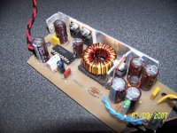
Recently, I did a 2-F DC-DC boost converter that puts out +19.5V (15-24V adjustable) @ something like 5-6A, using a non-isolated version of the ckt EVA describes. The controller is an SG3525, the MOSFETs are MTP75N06s, and the Schottky diode is an MBR2545CT. I used a bifilar-wound powdered-iron toroid, wound for ~27 mH pr winding. The centertap goes to +12V, and each end is alternately switched on and off, like a push-pull, but without DC-DC isolation. The spikes created at each end of the coil's winding are recovered by the double Schottky, filtered with a C-L-C section, and monitored for regulation. See the attached pic.
Hope this helps. If I figure out how to shring the size of the schematic file, I will post it here.
Steve
Well, there you have it. EVA's recommendation is kinda hard to argue with, because, unlike designing linear PSUs, more than just a little bit of design and testing is required to make a good design. Many people can design and fabricate rudimentary SMPSs, but it takes some effort to design a really good SMPS, or refine an existing one.
You could throw together a circuit like EVA describes, and it would work OK, but without the design refinements she describes (slow gate-drive, iron-powdered inductor, operating frequency and discontinuous operation), EMI & RFI will still be an issue. I suggest looking at several design notes before deciding on a strategy. Good design can mitigate RFI issues, it just takes a bit of knowledge, experience and patience.
Recently, I did a 2-F DC-DC boost converter that puts out +19.5V (15-24V adjustable) @ something like 5-6A, using a non-isolated version of the ckt EVA describes. The controller is an SG3525, the MOSFETs are MTP75N06s, and the Schottky diode is an MBR2545CT. I used a bifilar-wound powdered-iron toroid, wound for ~27 mH pr winding. The centertap goes to +12V, and each end is alternately switched on and off, like a push-pull, but without DC-DC isolation. The spikes created at each end of the coil's winding are recovered by the double Schottky, filtered with a C-L-C section, and monitored for regulation. See the attached pic.
Hope this helps. If I figure out how to shring the size of the schematic file, I will post it here.
Steve
Attachments
- Status
- This old topic is closed. If you want to reopen this topic, contact a moderator using the "Report Post" button.
- Home
- Amplifiers
- Power Supplies
- DC/DC 12V-15V inducterless Transformer Circuit needed