Workhorse said:Zero
Your Flyback cannot work with a 600V igbt with mains voltage at 240VAC, you need at least 1200V Igbt to do the job...
test clamping network for 600v igbt
 Princess of Asturias, Visigod Queen
It's not a matter of margin. Unless the tranformer is really well made to exhibit extremely low leakage inductance, the collector voltage will rise up to avalanche upn turn off. The schematic shows no clamp, only an RCD snubber that is probably not going to provide good enough clamping effect.
Capacitors across the diodes help in reducing the turn-off spike but make turn-on behaviour worse.
Capacitors across the diodes help in reducing the turn-off spike but make turn-on behaviour worse.
Let's make a rough guess:
According the newer schematic the refelected voltage would be 284V. Means already without leakage inductance the IGBT would see values close to 600V.
Say 310+284V=594V.
In the snubber cap 594V will mean a energy of 388uJ.
Then let's consider 5uH leakage. This will have stored 250uJ if we consider an switching event at 10A.
These 250uJ will be added to the 388uJ. So you get 638uJ in the snubber cap, means it will go to 762V.
Not only your IGBT is underrated also the 400V snubber cap.
And I it might be worse, because I have doubts that you will be able to realize 5uH.... The transformer itself is not so easy to design and you will additionally see an additional upwards transformed portion from all parasitic inductances of your secondary circuit loop(s).
Last but not least take care in this game.
In most offline applications people are considering 400V as relevant voltage for the safety isolation, which would required a layout AND transformer desgin that ensures 8mm creepage (EN60065, Table 11).
In your case with the high reflected voltage and leakage peak... well, in such a design the requirements might be even higher...
transformer completed
for 1kw gapped E70/33/32 transformer
for 1kw gapped E70/33/32 transformer
An externally hosted image should be here but it was not working when we last tested it.
An externally hosted image should be here but it was not working when we last tested it.
An externally hosted image should be here but it was not working when we last tested it.
An externally hosted image should be here but it was not working when we last tested it.
Keeping the windings away from the gap helps, this is achieved by using the outer portion of the winding space and leaving the inner portion unused. Using a gap in the three legs instead of a center-leg gap also helps a lot, but at the expense of stray magnetic fields that require some way of shielding.
You may consider several smaller transformers or the kind of iron powder toroid cores used for class D (low-perm low-loss RF iron powder and Arnold's MPP & Hi-Flux materials) as alternatives.
You may consider several smaller transformers or the kind of iron powder toroid cores used for class D (low-perm low-loss RF iron powder and Arnold's MPP & Hi-Flux materials) as alternatives.
...yes, litz would be a big step forward even in ungapped designs. See posting 16. In flybacks with large gap litz becomes a key factor.
The eddy currents are not just a small loss factor, in your design you will really get a brute hot spot in the windings which are close to the gap...
Of course for first looking if it works at all, the thick wires are better than nothing, but be carefull at higher power. You will find quite massive transformer heating burn the isolation in the inner area close to the airgap.
...I know HF litz is hard to get and pain to work with...
Regarding the other material like iron powder, MPP, cool u etc...
I am not sure that you really can make use of their higher saturation levels. These materials have remarkable higher core losses, so you still might have to use a lot of turns. Remaining advantage could be that you get them in lower permeabilities and might get rid of the air gap.
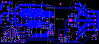
I'm sorry to say this but your PCB design is terrible. You may consider several improvements for much lower inductance in power loops. However, the most important improvement that you should consider is to add proper clearance (at least 5mm) between the secondary side and the primary side, and this includes the tracs going to the optocoupler.
BTW: Series inductance just after the secondary side diodes will only make the primary switch turn-off spike worse.
BTW: Series inductance just after the secondary side diodes will only make the primary switch turn-off spike worse.
Besides the giant loop inductances and missing safety, there seems to be a real circuit error:
Two of the four output caps should be connected before the 10uH chokes. In the PCB all are behind.
Looks like you are using software, without synchronisation between schematic and PCB?
Anyway, the most serious issue are the safety creepages & clearances.
I do not know to which standard Eva is referring, from my point of view you would need at least 8mm, may be even more. Referring to EN 60065 table 11.
If you tell me the worst rms values at 10% overvoltage of AC input for following voltages:
-DC-Rail: (probably close to 400V)
-Across primary of transformer at full power: xxxV?
-Voltage between collector of the IGBT vs protective earth: xxxV?
Then I can search for you the correct creepages and clearances in the EN60065.
I am referring to the EN 60065 (Audio, Video and similar). May be there are other standards, which define diffrent values..... You never know....
For 400V I am sure 8mm would be right if we assume dirt level II and and materials with low CTI value.
Dirt level II should be OK for in house use equipment.
If you are going to use materials with better surface creepage properties then the creepages could be reduced.
If the CTI value is ranging between 400...600: 5.6mm
If the CTI value is 600 or higher: 4mm
But nobody in DIY is able to control the CTI value of his materials. We have to use what we get and mostly without detailed specification.... So we should assume a low CTI value and design for 8mm.
Besides creepages also clearances are defined and there not only the rms value is relevant but also peak and DC values.
In our relevant voltage range a clearance of 5mm should be fine.
Glad to read that your peak values are lower than expected. In fact this value is looking like you have just a very minor peak....
Please note from the peak values I can tell you not the required creepages, but clearances only.
Clearances with 5mm is OK (referring to table 10).
For the creepage the standard is counting the rms value only.
From your schematic I would expect something like:
-300Vrms across the primary winding.
-430Vrms across the IGBT.
-380Vrms form collector of IGBT to protective earth.
If we consider 10% overvoltage then the highest voltage would be 473V.
EN60065 is giving creepage values for 400V (8mm) and
for 600V (12.6mm). Fortunately EN60065 is explicitely allowing to interpolate for voltages inbetween, -the found value must rounded up to the next 0.1mm grid.
For 473Vrms you will end up in 9.7mm creepage requirement.
BTW:
I guess I am not the only one who is curious about pictures and screen shots!")
Please note from the peak values I can tell you not the required creepages, but clearances only.
Clearances with 5mm is OK (referring to table 10).
For the creepage the standard is counting the rms value only.
From your schematic I would expect something like:
-300Vrms across the primary winding.
-430Vrms across the IGBT.
-380Vrms form collector of IGBT to protective earth.
If we consider 10% overvoltage then the highest voltage would be 473V.
EN60065 is giving creepage values for 400V (8mm) and
for 600V (12.6mm). Fortunately EN60065 is explicitely allowing to interpolate for voltages inbetween, -the found value must rounded up to the next 0.1mm grid.
For 473Vrms you will end up in 9.7mm creepage requirement.
BTW:
I guess I am not the only one who is curious about pictures and screen shots!
- Status
- This old topic is closed. If you want to reopen this topic, contact a moderator using the "Report Post" button.
- Home
- Amplifiers
- Power Supplies
- 1000w out offline flyback