Like the thread title says, here's my design that combines a 3 terminal series regulator (LM317, LM338, LT1085, etc.) with an adjustable 3 terminal shunt reference (TL431, LT1431).
The interesting thing about this design is how the regulators work together. The 3 terminal series regulators are designed to provide a fixed voltage between their output and adjust pins. Placing a resistor between those pins results in a constant current source which is perfect for biasing the shunt reference. So, the series regulator handles the biasing and output current duties while the shunt reference handles the voltage regulation.
This design should have a few advantages over the standard 3 terminal series regulator circuit.
- Better load regulation (true remote load sensing)
The load regulation is no longer limited by the resistance between the output of the regulator and the upper feedback resistor. However, the wiring/layout would have to be done properly in order to take advantage of this.
- Better ripple rejection (over a wider frequency range)
The 3 terminal shunt regulator will provide a low impedance for the 3 terminal regulator's adjustment pin.
- Better voltage stability (over time and temperature)
Most 3 terminal regulators are already pretty good in this respect, but the 3 terminal shunt regulator is better over time and temperature.
AND since the TL431 can be purchased for around $0.50 any added benefits come at very little extra cost! Not quite something for nothing but close.
It seems like the output noise would be reduced some as well since the TL431 is a reasonably quiet reference, but the series regulator's internal reference will probably be the limiting factor. Anyone have insight on possible noise performance?
I've simulated this circuit in Switchercad with the LT1431 and LT1085 and it requires more parts (for stability) than shown on the attached schematic because the LT1431 is a shunt reference with more access to the internal circuit than a 3 terminal shunt reference. The TL431 should work equally well though. RC1 on the schematic is there for two reasons. I've already done a PCB for this design and wanted to be able to implement the standard regulator circuit. That's now as easy as not populating VR1 and R11. The other reason is to provide a spot for a capacitor between the cathode and reference terminals in case there are stability problems.
Higher currents could be handled by using the series regulator to drive a pass transistor with feedback now taken from the emitter or source. A resistor could also be added between the regulator output and the output cap to form a low pass filter. Feedback would still be taken from the output cap but stability would need to be investigated.
Attachments
I must try this, I have a bunch of the parts sitting around.
I too wonder how this compares for noise front with using the simpler 'zener pedestal' (my thoughts on this here: http://www.acoustica.org.uk/t/3pin_reg_notes1.html). I have a hunch that there's not much in it, but if anything, at higher volatge - say much above 5v - a basic zener run at a decent 5-10mA will be quieter than a 431 with its internal noise is multiplied by the necessary gain.
I too wonder how this compares for noise front with using the simpler 'zener pedestal' (my thoughts on this here: http://www.acoustica.org.uk/t/3pin_reg_notes1.html). I have a hunch that there's not much in it, but if anything, at higher volatge - say much above 5v - a basic zener run at a decent 5-10mA will be quieter than a 431 with its internal noise is multiplied by the necessary gain.
Hi martin.
Nice web pages you have there. Please do let us know how it works if you cobble a circuit together.
The TL431 won't be better than a good zener in terms of noise but a good zener doesn't allow easy adjustment of the output voltage or regulation as good as the TL431.
Nice web pages you have there. Please do let us know how it works if you cobble a circuit together.
The TL431 won't be better than a good zener in terms of noise but a good zener doesn't allow easy adjustment of the output voltage or regulation as good as the TL431.
")
Hello,
The following schematic I have recovered from a new pcb with power supply out of a dump store.
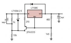
It is a conventional LT1085 with two resistors (460 ohm and 1K5) to set the output voltage.
To the left there is an additional circuit with LT1004 and P1015.
It looks like a way to narrow down the ripple of the input voltage (about 15V) for the regulator.
This way the regulator will see a constant ripple on the input, I presume.
This part puzzles me a bit as this could be done in a more simple way (like in the super raygulator).
The connection of the base of the P1015 to the adjust pin of the LT1085
Suggests there is a feedback between the LT1004 and the LT1085.
Does it contribute to a more stable voltage and/or lower noise?
Question: Can someone with EE-knowledge please explain how this circuit works exactly?
Best, Arjen.
The following schematic I have recovered from a new pcb with power supply out of a dump store.
It is a conventional LT1085 with two resistors (460 ohm and 1K5) to set the output voltage.
To the left there is an additional circuit with LT1004 and P1015.
It looks like a way to narrow down the ripple of the input voltage (about 15V) for the regulator.
This way the regulator will see a constant ripple on the input, I presume.
This part puzzles me a bit as this could be done in a more simple way (like in the super raygulator).
The connection of the base of the P1015 to the adjust pin of the LT1085
Suggests there is a feedback between the LT1004 and the LT1085.
Does it contribute to a more stable voltage and/or lower noise?
Question: Can someone with EE-knowledge please explain how this circuit works exactly?
Best, Arjen.
Attachments
Hello,
Can someone please respond to my question in the previous post?
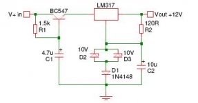
In the super raygulator as in the attached schematic a capacitance multiplier preceding the regulator will take care of the high frequency disturbances like in the Flea regulator of Pinkfish media forum.
Now I have an additional question to this super Raygulator: why are there two zeners in the connection between the adjust pin and ground?
Best, Arjen.
Can someone please respond to my question in the previous post?
In the super raygulator as in the attached schematic a capacitance multiplier preceding the regulator will take care of the high frequency disturbances like in the Flea regulator of Pinkfish media forum.
Now I have an additional question to this super Raygulator: why are there two zeners in the connection between the adjust pin and ground?
Best, Arjen.
Attachments
Hello,
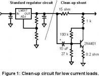
While I am at it another question pops to mind. The so called Wenzel circuit offers a clean up after the regulator, like the enclosed schematic shows. See www.wenzel.com or http://www.diyaudio.com/forums/showthread.php?s=&threadid=7414&perpage=10&pagenumber=5
Can one say that the methods mentioned in my previous posts have a different function?
Or are they intended to achieve the same. And if so, what is a better approach: to filter before the regulator, as a part of the regulator, after the regulator or may be an intelligent combination? You might say: for what purpose? Well, let us focus on a supply for a digital clock of a simple sand preamp.
I wonder who might enlighten some answers?
Best, Arjen.
Attachments
Hello,
Per-Anders, thanks for your contribution. I am indeed not aware of hijacking this thread. My question in post 7 was about a 3 terminal series regulator (LT1085) with a 3 terminal shunt reference (LT1004). Which is the heading of this thread. My other two questions were related to this, at least that was my intention. I have seen and experienced worse on this forum. However, if the moderator considers this hijacking I am open to start a new thread.
One way or the other, would anyone with EE-knowledge please be so kind to respond to the content of my initial question in post 7 ?
Best, Arjen.
- Status
- This old topic is closed. If you want to reopen this topic, contact a moderator using the "Report Post" button.
- Home
- Amplifiers
- Power Supplies
- 3 terminal regulator with 3 terminal shunt reference