Steven,
With reference to the holey brace. How are you going to tightly fit the driver magnet againt the holey brace? The brace's primary purpose is to shunt driver energy across more panels. A direct path of solid material from driver magnet to back panel makes this more effective.
As well it looks like the hole-to-brace ratio is such that you won't gain most of the 3rd (small) benefit of the holey brace. (to disrupt side-to-side standing waves). Also, just a gut feeling, but i suspect a lot of stress at the corners of the cutouts. A much larger radius would help.
As pretty as they are, these holey braces are short of the design goals for them. I hate to say it, but it is worth considering doing them over again, if not too late (ie if you are going to do them, might as well do them right -- and with the CNC not hard)
dave
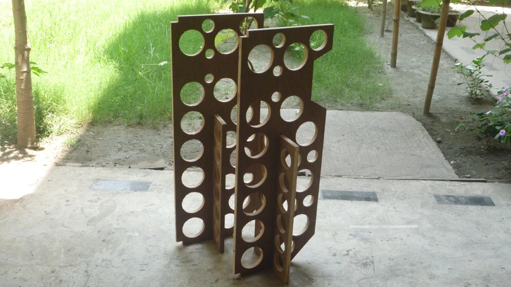
I didn't plan on snugging the brace against the driver. I believe with the density and quality of the plywood I shouldn't have much of a problem shunting the driver's energy. As for the holey brace, it's 3/4" x 1" and should provide adequate panel stiffening. Each brace is offset 3/4" from the center of the panel allowing for the "side-to-side standing waves" to be disrupted. Also the braces are terminated in the middel of each adjacent opening. Trust me, the enclosure is rock solid and I don't see any practical way of making it more rigid other than by adding another layer of 3/4" material on the outside or increase the internal bracing to complete and utter overkill.
I've build high powered subwoofer cabinets (2000 watts+) with less bracing and cheaper material and never experienced ill-panel resonance problems or compromised structural integrity. I have serious doubt that such a small driver will come anywhere near to testing the structural integrity of this cabinet. Though if it does, I'll have no problem redesigning my bracing and starting from scratch.
I've build high powered subwoofer cabinets (2000 watts+) with less bracing and cheaper material and never experienced ill-panel resonance problems or compromised structural integrity. I have serious doubt that such a small driver will come anywhere near to testing the structural integrity of this cabinet. Though if it does, I'll have no problem redesigning my bracing and starting from scratch.
I don't doubt it satisfies the goal of bracing the cabinet... it misses out on the other 2. Subsequently you will loose some downward dynamic range, and the Alpairs are certainly capable.
The middle of each adjacent opening is the weakest connection point.
I applaud the effort, but those that are following this thread as an example for their build need to know the short-comings of your execution of the holey brace.
Zia's execution takes full advantage.
dave
Also the braces are terminated in the middel of each adjacent opening
The middle of each adjacent opening is the weakest connection point.
I applaud the effort, but those that are following this thread as an example for their build need to know the short-comings of your execution of the holey brace.
Zia's execution takes full advantage.
dave
The project hasn't failed. Lots of people are very happy with Pensils with no bracing at all. Yours will be, IMHO, a step up from that. You will have a great speaker.
But it is important to point out (for the thousands looking on) that your holey brace miss the full potential of its application.
dave
But it is important to point out (for the thousands looking on) that your holey brace miss the full potential of its application.
dave
I would've thought the brace that I built would've distributed the panel forces evenly along the entire brace system by having them stepped in the manner that I did. Also increasing the width to a full 1-1/2" inch in the middle and 1" veins throughout it's entire construction. In my eyes at the time it was a superior way to brace the cabinet. I just thought the hole's that were used in the plans were a simple way to do bracing because not many people are willing to do a window pane type brace. It's easy to buy a 3" hole saw and go to town, thus catering to the entry level DIY people out there.
As for bracing the rear of the driver, I can CNC a sliver to match the arch of the half-circle cutout and glue it to the brace, giving me a flat edge to hold the driver with. Hopefully this helps to salvage the project.
As for bracing the rear of the driver, I can CNC a sliver to match the arch of the half-circle cutout and glue it to the brace, giving me a flat edge to hold the driver with. Hopefully this helps to salvage the project.
The circlular hole was choosen because it leaves the strongest brace, It also forces a maximum 35-45% holes. That means that 35-45% of the internal waveforms will reach side to side, and their distribution will be hetergeneous, so weaker. One also gets a conncurrent decrease in the standing wave energy being imparted into the side panels. The rest (55-65%) will form higher frequency standing waves, higher frequencies at which the damping is much more effective. With more panel volume the holey brace also has more capability to damp & dissipate energy inside the box where it is less objectionable than if the energy is dissapaited outside the box.
I would recommend that.
dave
As for bracing the rear of the driver, I can CNC a sliver to match the radius of the cutout and glue it to the brace, giving me a flat edge to hold the driver with. Hopefully this helps.
I would recommend that.
dave
I actually didn't bother with alignment of the grain. Though it did take a few minutes to place by hand all of the parts on the sheet correctly. Here are a few more pics. I'll upload the completed photos in a couple of hours.
I was actually referring to what looks like quite decently aligned grain pattern on the parts labeled front and back.
Don't be dissuaded by commentary on the patterns used on your bracing - this likely won't be your last speaker project, and since they didn't take very long to whip up on your CNC, a new set could probably be produced before 3 or 4 more folks post about it on the forum. (and certainly a lot faster than cutting all those holes in Baltic Birch / Apple plywood with a hole saw )
Even when features of design or fabrication / joinery details on some of Dave & Scott's enclosures might appear to be intended to simplify construction, that's not always the case. And of course, there is no "absolutely right" way to design or build
anything
Last edited:
Maybe I should just stick to open baffle speakers next time ") Hahahaha. Oh well, you live, you learn. I'm sure they'll sound fine in the end.
Hahahaha. Oh well, you live, you learn. I'm sure they'll sound fine in the end.
I've run out of this material so building more is out of the question right now. I'd have to order more, but at $275 USD per sheet it's not likely going to happen any time soon.
Hahahaha. Oh well, you live, you learn. I'm sure they'll sound fine in the end. I've run out of this material so building more is out of the question right now. I'd have to order more, but at $275 USD per sheet it's not likely going to happen any time soon.
Also worth mentioning that the use of volume fill in the Pensils, reduces the effectiveness of the 3rd/standing wave function, vrs something like a Fonken with only wall lining.
So with the shim, you are most of the way there.
My buddy always told me, if you aren't falling down you aren't getting better.
dave
So with the shim, you are most of the way there.
My buddy always told me, if you aren't falling down you aren't getting better.
dave
... this material ... $275 USD per sheet
What are you using? That is up into stranded bamboo ply territory.
dave
What are you using?
First post:
I programmed the parts on my CNC router and cut them out of 13-ply void free plywood
Maybe I should just stick to open baffle speakers next time
You will find that these will have intrinsic character that can never be achieved with an OB.
dave
First post
I programmed the parts on my CNC router and cut them out of 13-ply void-free plywood
That doesn't explain it. Here we pay <$50 / sheet (5'x5' sheets). The more upmarket architectural grades with veneers can reach up $150 (4x8 sheets).
So either Steve has something special, or got hit with a lot of shipping.
dave
You will find that these will have intrinsic character that can never be achieved with an OB.
dave
Funny you say that. OB guys will say the same thing about "box speakers" such as this.
As for the plywood I'm using, It's special domestic plywood made specifically for a large project the company I work for was doing a couple years ago. Yes, I order custom made plywood straight from the manufacturer. Babmboo core doesn't go for nearly that much per 4x8 sheet for me. My cost per sheet of stranded bamboo is $40-60 depending on source and it's always superb quality. The price you stated for architectural plywood with veneer is average for low-mid grade stuff. The veneered plywood we deal with ranges from $150 upwards to $8-900 for AA exotics.
Specifically, i'm using 13-ply birch core void-free AA yellow pine. The plywood has zero voids and zero overlaps in the core. It's domestically made as to guarntee quality. I've also applied a sheet of paper backer to one side (inside of cabinet) in an effort to kill reflections a little. Not sure if the paper backer will make a difference or not but I thought that it surely couldn't hurt.
Cheers,
Steven
Funny you say that. OB guys will say the same thing about "box speakers" such as this.
Yes, i hear that in OBs too... much prefer to live with the shortcomings of a well made box.
dave
Also worth mentioning that the use of volume fill in the Pensils, reduces the effectiveness of the 3rd/standing wave function, vrs something like a Fonken with only wall lining.
dave
So let me ask you. How do you counter this? How do you have the both of best worlds? In which scenario would you not HAVE to use any form of lining or fill at all besides for the obvious answer of an OB design? Are you suggesting that one should pack the bottom portion of the cabinet with stuffing and leave the top free instead of evenly distributing the stuffing throughout? Do explain.
- Status
- This old topic is closed. If you want to reopen this topic, contact a moderator using the "Report Post" button.
- Home
- More Vendors...
- Planet 10 hifi
- Steven's Alpair 10.2 Pensil Build Log