For high frequency you need a toroidal transformer. Its best to use two since that half's the voltage they see. Two 120V primary 6V secondary transformers work good, that will give you a 40:1 step up. Use a HV power supply from a photocopier for a bias. I made a little diagram in ms paint. If it does not work just flip the wires to one transformer, they can be working against each other. The bias supply can be very low current. You can run the 6V side in parelell to get a lower independence also. Use a wire wound resistor to get the independence to 8 ohms, this will protect the amp from occilation also.
Attachments
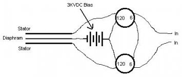
Two 120V primary 6V secondary transformers work good, that will give you a 40:1 step up.
The way you have it drawn, you have both the primaries and the secondaries wired in series, so you'd get 20:1. You'll need to put the "6V" windings in parallel to get 40:1. I suspect that's what you meant
")
ak_47_boy said:For high frequency you need a toroidal transformer. Its best to use two since that half's the voltage they see. Two 120V primary 6V secondary transformers work good, that will give you a 40:1 step up. Use a HV power supply from a photocopier for a bias.
This is not the safest suggestion I've ever seen here. The transformer insulation is rated at 120 V, perhaps three times that to cover overvoltages, but 3 KV? At that point it needs better isolation than you're likely to get from a power toroid.
Long story short, this is dangerous as hell. If you're lucky a failure (quite possible under these conditions) will only blow up your amplifier. If you're unlucky it'll take out your house. Find another way.
Hi,
rated at 120V? Sorry, but that is utterly rubbish. The insulation of a Tranny is rated much higher than its working voltage. Have a look at the datasheets of the manufacturers. Between primary and secondary a lot of trannies (over here in Europe) are tested to withstand 4kV (sometimes 5kV) and the insulation between primary/primary or secondary/secondary is often more than 500V. So If You use trannies with a single primary (120V or 230V) and one or more secondaries (6V, 9V, 2x6V, 2x9V) , You´ll have a insulation strength of 4kV(peak). Connecting 2 of such trannies in parallel on the lowvoltage side and in series on the highvoltage side You can safely drive ~2.8kVrms (~73Vrms on the lowvoltage side with 230V/6V trannies). With a vacuum dipped tranny the insulation ratings are even higher, but since the dipping varnish exceeds the stray capacitance this might lead to other probs.
2.8kVrms is sufficient to drive mid sized to big panels with a d/s up to 1.5mm to earshattering levels. For a small tweeter with low capacitance it might be useful to use 4 trannies in series (highside) - parallel (lowside) to get the impedance down and low enough.
I´d suggest to use a couple of single primary-single secondary toroid trannies of 30W-80W power rating.
If You use EI-Type trannies You might get bandwidth problems because of the high stray capacitance. In this case it can help to parallel more pairs of trannies like it is done in the picture with 6 of it.
For the bias-supply (which is what You´re Q was about originally?) You may use two simple offtheshelf trannies of very small powerrating (~1W is more than sufficient) and connect thier lowvoltage sides together (120V-12V-12V-120V). You´ll have the 120V from the powerline at the output of the second tranny again, but dissected galvanically from the power feed. Add several steps of a simple voltage doubler cascade (Cockroft-Walton, 2Diodes-2Capacitors peer step) and a high ohmic value resistor (>10Meg, best a series connection of a couple of resistances to manage the high voltage safely) from the output of the circuit to the membrane of the ESL. If You use the following circuit instead of a simple series resistor You have a nice charging indicator for Your membrane.
When charging up the membrane, the cap´s voltage will rise. When the treshold voltage of the neon bulb is reached it will blink, thereby discharging the cap and charging the membrane and the process begins new. The freqency of the blinking is quite high when powering up but decreases fast. It is an indicator for how good (no leakage, freqency is very low ~0.1Hz) or how bad the panel is built (if there are leaks blinking frequency is considerably higher than 0.1hz). Since this simple circuit works comparably to a switch that is just closed when needed, the Bias-supply is isolated from the panel, thereby reducing possible humming or other noise.
jauu
Calvin
rated at 120V? Sorry, but that is utterly rubbish. The insulation of a Tranny is rated much higher than its working voltage. Have a look at the datasheets of the manufacturers. Between primary and secondary a lot of trannies (over here in Europe) are tested to withstand 4kV (sometimes 5kV) and the insulation between primary/primary or secondary/secondary is often more than 500V. So If You use trannies with a single primary (120V or 230V) and one or more secondaries (6V, 9V, 2x6V, 2x9V) , You´ll have a insulation strength of 4kV(peak). Connecting 2 of such trannies in parallel on the lowvoltage side and in series on the highvoltage side You can safely drive ~2.8kVrms (~73Vrms on the lowvoltage side with 230V/6V trannies). With a vacuum dipped tranny the insulation ratings are even higher, but since the dipping varnish exceeds the stray capacitance this might lead to other probs.
2.8kVrms is sufficient to drive mid sized to big panels with a d/s up to 1.5mm to earshattering levels. For a small tweeter with low capacitance it might be useful to use 4 trannies in series (highside) - parallel (lowside) to get the impedance down and low enough.
I´d suggest to use a couple of single primary-single secondary toroid trannies of 30W-80W power rating.
If You use EI-Type trannies You might get bandwidth problems because of the high stray capacitance. In this case it can help to parallel more pairs of trannies like it is done in the picture with 6 of it.
An externally hosted image should be here but it was not working when we last tested it.
For the bias-supply (which is what You´re Q was about originally?) You may use two simple offtheshelf trannies of very small powerrating (~1W is more than sufficient) and connect thier lowvoltage sides together (120V-12V-12V-120V). You´ll have the 120V from the powerline at the output of the second tranny again, but dissected galvanically from the power feed. Add several steps of a simple voltage doubler cascade (Cockroft-Walton, 2Diodes-2Capacitors peer step) and a high ohmic value resistor (>10Meg, best a series connection of a couple of resistances to manage the high voltage safely) from the output of the circuit to the membrane of the ESL. If You use the following circuit instead of a simple series resistor You have a nice charging indicator for Your membrane.
An externally hosted image should be here but it was not working when we last tested it.
When charging up the membrane, the cap´s voltage will rise. When the treshold voltage of the neon bulb is reached it will blink, thereby discharging the cap and charging the membrane and the process begins new. The freqency of the blinking is quite high when powering up but decreases fast. It is an indicator for how good (no leakage, freqency is very low ~0.1Hz) or how bad the panel is built (if there are leaks blinking frequency is considerably higher than 0.1hz). Since this simple circuit works comparably to a switch that is just closed when needed, the Bias-supply is isolated from the panel, thereby reducing possible humming or other noise.
jauu
Calvin
Calvin, I beg to differ. Possibly the insulation voltage might be that high in Europe, but remember the line voltage is double that in the States so insulation values might be lower here. On top of which, it's not a simple matter of saying one transformer is rated at 4 kV and another at 4 kV, so the two in series would be rated at 8 KV: the leakage will not be identical for the two transformers, so ironically the one which leaks less will have more voltage on it, and be more prone to flashover.
Your schematic seems to go round this problem by assuming the driving circuit has a low impedance to ground, thus equalising the voltage stress across the transformers, but that's vulnerable to a loose connection. It's also dodgy if VPol floats very much with respect to ground.
Looking at an insulation strength of 4 kV + 4kV and concluding you can drive 8 kV peak-to-peak leaves no room for error or component variance. I still recommend purpose-built transformers for this task.
Hi,
I just can repeat what I wrote before: Check the Datasheets! Knowing that the line-voltage in Europe is twice that of the US, a figure of 4kV doesn´t need to apply to US-gear, right!
One should also consider that the flashover-treshold comes down with increasing frequency and thats where a leakage imbalance would matter too! This is countered by the fact that music normally doesn´t consist of much high frequency energy (but keep in mind, when such signals might occur e.g. when measuring)
Tested to 4kV means tested for a certain period of time with sinusodial signals of 50Hz frequency. The shorttime flashover treshold is considerably higher.
To reach the treshold voltages of the trannies insulation You will have to provide primary voltages that are higher than most of the amps on the market could provide anyhow (remember that 100W@8Ohms needs less than 30Vrms).
I´ve had the second best results with my panels using simple toroids. The best result I got with a Amplimo/Plitron toroid costing 10 times the price (luckily it was just slightly better outside the desired freq-range, so I use my small toroids happily on )
And even though I stressed the toroids and Panels quite heavily they have not given up yet, while most of the purpose wound trannies find themselves on the scrapyard because of too weak insulation!
jauu
Calvin
I just can repeat what I wrote before: Check the Datasheets! Knowing that the line-voltage in Europe is twice that of the US, a figure of 4kV doesn´t need to apply to US-gear, right!
One should also consider that the flashover-treshold comes down with increasing frequency and thats where a leakage imbalance would matter too! This is countered by the fact that music normally doesn´t consist of much high frequency energy (but keep in mind, when such signals might occur e.g. when measuring)
Tested to 4kV means tested for a certain period of time with sinusodial signals of 50Hz frequency. The shorttime flashover treshold is considerably higher.
To reach the treshold voltages of the trannies insulation You will have to provide primary voltages that are higher than most of the amps on the market could provide anyhow (remember that 100W@8Ohms needs less than 30Vrms).
I´ve had the second best results with my panels using simple toroids. The best result I got with a Amplimo/Plitron toroid costing 10 times the price (luckily it was just slightly better outside the desired freq-range, so I use my small toroids happily on
)And even though I stressed the toroids and Panels quite heavily they have not given up yet, while most of the purpose wound trannies find themselves on the scrapyard because of too weak insulation!
jauu
Calvin
Gentlemen, the insulation of a winding to chassis (which is what is tested by 5kV flash testers) is a rather different issue to the maximum voltage a transformer can withstand from one end of a winding to the other. It strikes me that a winding designed for 240V (or 120V, for that matter) will have wire chosen with an enamel thickness sufficient to withstand the working voltage. Scaling that by a factor of ten to drive electrostatic panels sounds risky. Although the voltage from one turn to the adjacent turns will not be great, the 240V (or 120V) winding may well be wound in more than one layer and the voltage between layers would be very high in the proposed use. If it broke down, you could probably kiss your amplifier output stage goodbye.
Edit: Rather than speculating, it would be helpful to know what gap the tweeters have, and their area. Or their capacitance, or any combination of two out of three. Anything, really.
Edit: Rather than speculating, it would be helpful to know what gap the tweeters have, and their area. Or their capacitance, or any combination of two out of three. Anything, really.
EC8010 said:It strikes me that a winding designed for 240V (or 120V, for that matter) will have wire chosen with an enamel thickness sufficient to withstand the working voltage. Scaling that by a factor of ten to drive electrostatic panels sounds risky. Although the voltage from one turn to the adjacent turns will not be great, the 240V (or 120V) winding may well be wound in more than one layer and the voltage between layers would be very high in the proposed use.
Toroids have long winding area's, that's why the windings often consist of only one layer. Even if they have more layers then there is good chance there is additional isolation between the layers (makes placing the next layer easier, smooth surface). EI cores often don't have additional isolation between layers because there is simply no room for it (winding window is short,many layers required and winding area height is limited by hole size in core).
Therefore EI's are prone to isolation failure in this application while toroids do very well.
The fact that toroids have so few layers also accounts for their good frequency response, small winding height = less leakage.
maudio said:The fact that toroids have so few layers also accounts for their good frequency response, small winding height = less leakage.
Interesting. I thought the better HF response of toroids was down to the better magnetic path of the core - no sharp bends or changes in permeability to cause leakage, and therefore leakage inductance. Thoughts?
EC8010 said:
Interesting. I thought the better HF response of toroids was down to the better magnetic path of the core - no sharp bends or changes in permeability to cause leakage, and therefore leakage inductance. Thoughts?
That has little to do with it.
Leakage is mostly caused by the fact that the different windings never share all magnetic field lines, there are always some lines that don't go through all windings and so magnetic coupling is never 100%.
This is simply caused by the physical arrangement of the windings. They can never be all in exactly the same physical plane.
The thinner the layer of combined windings is the better. Since having few layers also reduces capacitance there is a double benefit for high frequency response.
A common way to reduce leakage is to interleave the primary and secondary in several layers. But the price for that is higher internal capacitances, which reduces the positive effect on high freq response.
In fact it's possible to calculate a pretty good estimate of what leakage for a given transformer will be, based on the arrangement of the windings and their sizes. Have a look at the RDH4, there is a whole chapter on the subject.
ak_47_boy said:[B............Two 120V primary 6V secondary transformers work good, that will give you a 40:1 step up............. You can run the 6V side in parelell to get a lower independence also. ............ [/B]
DSP_Geek said:
This is not the safest suggestion I've ever seen here. The transformer insulation is rated at 120 V, perhaps three times that to cover overvoltages, but 3 KV? At that point it needs better isolation than you're likely to get from a power toroid.
Find another way.
The easiest way to find out if the insulation will take the voltage is to try it !!!
Anyone have 2 transformers - 240/60v and 240/6v ??
That should give 2.4Kv on the output.
Andy
The easiest way to find out if the insulation will take the voltage is to try it !!!
You can try it of course. But what works today might not work tomorrow. If the insulation materials pick up moisture and airborne contaminants, there can be an aging effect resulting in degradation of voltage stand-off. Also, a brief voltage peak might cause no breakdown, but sustained voltages could "punch through". Finally, once leakage starts, carbon tracking and dust attraction can make it worse and worse.
- Status
- This old topic is closed. If you want to reopen this topic, contact a moderator using the "Report Post" button.
- Home
- Loudspeakers
- Planars & Exotics
- Powering Electrostatic Tweeters