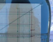
I did some tests today- I drew some lines on the stretcher table, put a piece of film on it and traced over the lines, then stretched the film tight. Here's the result, from one corner of the table. The other three are about the same...
You can see more photos on my website at this address:
http://mark.rehorst.com/ESLs/diaphragm_stretcher.htm
I_F
You can see more photos on my website at this address:
http://mark.rehorst.com/ESLs/diaphragm_stretcher.htm
I_F
Attachments
your website was a great inspiration to me when I was considering building my set of electrostatic speakers. Thanks for sharing, it's nice to see your information is still out there. That round inner-tube stretcher picture has got to be almost old enough to vote... ")
I've got a printout of that page in my ESL binder that has yellowed and I consider it critical to my actually building my speakers.
Just wanted to say thanks,
Sheldon
I've got a printout of that page in my ESL binder that has yellowed and I consider it critical to my actually building my speakers.
Just wanted to say thanks,
Sheldon
Thanks very much for your assistance with the stretching problem. I hope to make a stretching table tonight and I am much more confident about getting consistent results. Have you had to re-glue the stators on your ESL63s I have several that have come adrift, if so what adhesive did you use
Stuart
Stuart
405man said:Thanks very much for your assistance with the stretching problem. I hope to make a stretching table tonight and I am much more confident about getting consistent results. Have you had to re-glue the stators on your ESL63s I have several that have come adrift, if so what adhesive did you use
Stuart
I'm glad you're able to use the info.
Yes, I completely rebuilt all the drivers in my ESL-63s. I took off all the stators, cleaned them up and reglued them using the same contact cement that I use for the diaphragms. Scotchgrip 4693H purchased from McMaster-Carr.
The first step in removing the stators is to unsolder the connecting clips. You will have to push against the stator as the solder is melting to get the parts to separate. Don't burn your fingers! Be carful not to break the stator as you pull it off the grid. The old glue lets go pretty easily, but if anyone ever did any repairs with other types of glue they might be stuck on there pretty tightly.
I cleaned the stators with a scraper first to remove chunks of old glue, then wiped them using a solvent called "goof-off" which is sold for the purpose of removing wax, glue, chewing gum, etc. from household items. The old glue seems to have been some sort of hard wax- it scrapes off easily. When you're using a scraper, be careful not to overdo it and peel the copper off the stator.
I also cleaned the grids with the scraper and goof-off.
I applied the glue only to the plastic grid, then laid the stator back in place on top of the glue. You have to be careful not to use too much glue or it will come through the holes in the stator. I let the reglued stators sit overnight to allow the glue to harden. After the glue is hard, the stators are soldily attached to the plastic grid. If you push on them to test the glue joints it feels like the stator will break before the glue will let go.
After regluing the stators and installing a new diaphragm, I masked the diaphragm with blue masking tape (lets go easily), and used circles cut from post-its to mask off the screw holes in the center of the driver. I matched the original diaphragm masking pattern. The masking tape covered the sides of the grid, too, so it wouldn't get any Licron on it. After everything was masked, I sprayed the Licron, then let it sit for a few hours.
Peel off the masking tape and post-its, then use a soldering iron to melt holes in the film around the center posts. Inspect with a 5X or 10X loupe and be sure to remove any hairs of melted plastic that form.
Bolt the driver back together, bolt it back into its frame, wire it up and test it. If it works OK, go to the next one...
I used a pretty slow process of rebuilding one driver at a time and testing each in the speaker as it was completed. I think if I were to ever do it again (I may have to in 20 years or so), I'd probably rebuild all the drivers at once and have a test power supply prepared for testing the drivers. I did this job shortly after moving to Phoenix and a lot of my stuff was still in boxes so I had to make do with the stuff I could locate quickly.
I encountered two problems while rebuilding the speakers. There are a lot of solder joints where the grid clips attach to the stators. I managed to miss one or two of them. They make themselves known by generating lots of noise and distortion. Be sure you solder them all back in place!
The other problem happened when i had to replace one diaphragm 4 times until I realized that the tube on the stretcher table had a hole in it. The air pressure was dropping and releasing tension on the film before I got the stator glued to it. This is why I recommend rounding the corners and edges on the stretcher table. Doh!
I_F
Thanks again for the info. I have been out and bought some material to build the table and an inner tube. My Mylar is 25 inches wide and I recon I need 4 inches each side to go round the tube and attach to the under side, that leaves 17 inches and each panel is 7.75 inches so I hope to do 2 at a time to save wasting to much film. I am going to cut the corners off the table so that I end up with an irregular octagon. I shall try to post some photos when I get it made. I can not find Scotchgrip 4693H in the UK but my friend is in the US on holiday and will try to bring some back next week. Once I get the panels rebuilt I want to build some 6 panel 63s like the 989s and I have bought some steel box section to make the frames. I noticed that the early 63s have the panels attached directly to the side extrusions but the later ones have them attached to rails which sits in rubber mounts top and bottom but I don’t know if this was just for production reasons. You can lift the complete 4 panel assembly out in one piece from the later speaker. I have yet to decide how to mount my panels to the steel frames or how to mount the dust covers. I would be interested to know what you think of the Quads, I have come to the conclusion that all loudspeakers are a compromise and the Quads are still one of the best.
Stuart
Stuart
I Forgot
I have always wondered why you have to burn a hole through the diaphragm on the ESL63 .Couldn't you just put a spacer /diaphragm support at that spot and use the screw holes on the outer edges to hold the two halves of the frame together. I thought that would allow higher voltages and improve sensitivity.
Thanks
Andrew
Atom66 said:I Forgot
I have always wondered why you have to burn a hole through the diaphragm on the ESL63 .Couldn't you just put a spacer /diaphragm support at that spot and use the screw holes on the outer edges to hold the two halves of the frame together. I thought that would allow higher voltages and improve sensitivity.
Thanks
Andrew
Clamping the diaphragm at those points instead of letting it move will somewhat reduce the ability of the diaphragm to swing and I would expect that to reduce sensitivity. It would probably also have some effect on the resonances, but I can't say it that would matter or not. You might be able to use higher voltage, but they're already >5kV. If you go any higher I expect the corona becomes unmanageable.
The main reason the speakers are screwed together in the middle is because the corner holes are used to attach the drivers to the frame. Without the center holes there's nothing to hold the driver together once you remove the corner screws. It would be very easy to destroy a diaphragm if the driver came apart as soon as the screws were removed from the corners.
I_F
Hi Mark
I didn't realise you were I_F. I must repeat what Sheldon says: many thanks for the inspiration back in the day.
Back on topic, how does the tube stretcher compare with the more mundane tape and spring method??
Regards
Ed
www.vitalstates.co.uk
I didn't realise you were I_F. I must repeat what Sheldon says: many thanks for the inspiration back in the day.
Back on topic, how does the tube stretcher compare with the more mundane tape and spring method??
Regards
Ed
www.vitalstates.co.uk
Vitalstates, your website just made my web browser (Safari) conk-out due to Java overload. Perhaps you could have a home page without all the animations.
Sorry about the OT post.
Neat stretcher and website, by the way, I_Forgot. I will definately try this method when/if I build some ESLs. I have a nearly endless supply of inner tubes, as I work at a bike shop.
Max
Sorry about the OT post.
Neat stretcher and website, by the way, I_Forgot. I will definately try this method when/if I build some ESLs. I have a nearly endless supply of inner tubes, as I work at a bike shop.
Max
Atom66 said:Hi
What are the dimesions of your stretching table ? I am going to be building one soon to rebuild my ESL63 panels
Thanks
Andrew
It's about 645mm x 440mm. I built it about 18 years ago and it happens to be large enough for the Quad ESL-63 drivers so I continue to use it. If I were building one specifically to rebuild ESL-63 drivers I would make the dimensions proportional to those of the driver. Make the perimeter of the table a bit larger than the circumference of of a bike wheel so that the tube has to stretch over the table to fit.
vitalstates said:Hi Mark
I didn't realise you were I_F. I must repeat what Sheldon says: many thanks for the inspiration back in the day.
Back on topic, how does the tube stretcher compare with the more mundane tape and spring method??
Regards
Ed
I have never tried that technique. I hit on the pneumatic stretcher pretty early then moved on to other problems.
Thanks for the kind words. I used to get a lot of email about the site, but the I terminated the email address on the old web page and didn't get around to updating the page so I sort of disappeared for a while. I'll be taking the old pages down soon and leaving a forwarding link to the new stuff. The gmail address should be permanent, unless google starts charging for it. So far posting the address in a graphic has prevented most of the spam bots from getting the address.
Cheers!
I_F
maxro said:Vitalstates, your website just made my web browser (Safari) conk-out due to Java overload. Perhaps you could have a home page without all the animations.
Max
Hi Maxro
There are only 2 applets on there, but I take your point, I'll reduce it to one....there must be other safari users out there that are suffering.
Regards
Ed
The spring and tape method is great, I use it all the time now. The requirements are a good flat surface that the tape can stick to. I use a mirror which also helps me see anything on the glass before I put the mylar down.
The method (with props to Rob M. at ER audio who as far as I know invented the brilliant technique) involves a small spring scale, a free Formica sample attached to the spring scale, and a lot of pieces of packing tape.
Start by attaching the 4 corners of the mylar down to secure it to the surface. Then you start at the middle of one side and stick a small piece (say 3" long) of packing tape to the Formica square on the end of the small spring scale with most of it hanging off. You attach the other end to the mylar (say the last 1 inch) being careful to only attach it to the mylar and not the surface next to it. You then pull the scale parallel to the surface perpendicular to the edge of the mylar until the scale reads your desired tension. Then you push the middle of the tape against the surface and in a rotating motion unpeal it from the scale and onto the surface. The next piece is directly opposite the previous piece so the tension is in opposition. Work your way from middle to the both edges, then turn 90 degrees and work the other two sides from middle to edges. It produces remarkably uniform and even tension a couple inches away from the edges.
The downside to this technique is that the tension isn’t as even at the very edges, so you have a bit of waste due to making the mylar piece larger than necessary to use the center part. But I suspect the wastage is pretty similar to inner-tube method. The lowest wastage in my experience is heat shrinking, and is hard to beat for non-tension critical applications. When building my big ESL’s, I was almost forced into heat shrinking due to the width of the mylar vs. the width of the panel I wanted to make.
As a side note, the tape and spring scale method would work great for building curved panels where you ideally only want to tension in one direction.
Sheldon
Thanks for the kind words
The problem is the content isn't really very new. I've got to get off my butt and build something interesting that is worth putting on the site. I did add a ton of pictures in photo-albums. Nothing too interesting. I'm refurbishing quads and a pair of citation II amps. I've got a set of active 2-way MTM spakers on the drawing board, but I probably won't get to them for a couple more months.
Sheldon
- Status
- This old topic is closed. If you want to reopen this topic, contact a moderator using the "Report Post" button.
- Home
- Loudspeakers
- Planars & Exotics
- Pneumatic Diaphragm Stretcher Performance