Lifter vehicle + plasma tweeter driver
Coupling transformers in series could work
")
But you would need somthing to drive them with.
A tesla coil shouldnt be all that difficult. I found another schematic for a plasma
tweeter's RF/driver stage using a 6146 pentode. Easier to work with compared to
the 813. I may start the build based on this 6146.
bigwill said:Would you really need a 20kV voltage swing? Hmm, maybe it is better to do what you said
Argh, why can't this be more simple
I guess I'll have to build a tesla coil some day
Coupling transformers in series could work
But you would need somthing to drive them with.
A tesla coil shouldnt be all that difficult. I found another schematic for a plasma
tweeter's RF/driver stage using a 6146 pentode. Easier to work with compared to
the 813. I may start the build based on this 6146.
Lifter vehicle + plasma tweeter driver
Not a full swing, but some audio signal floating around 20.
The lifters uses >20 kV. If the electrodes had a narrower spacing, then a such transducer could maybe operate at lower voltages. But this may again result in excessive formation of ozone and nitrogen–oxides
To accomplish 'a lighthest possible operation', voltage tuning should be of virtue.
bigwill said:Would you really need a 20kV voltage swing?
Not a full swing, but some audio signal floating around 20.
The lifters uses >20 kV. If the electrodes had a narrower spacing, then a such transducer could maybe operate at lower voltages. But this may again result in excessive formation of ozone and nitrogen–oxides
To accomplish 'a lighthest possible operation', voltage tuning should be of virtue.
On plasmatweeter.de Mr. Haumann mentions the IML which worked with PWM. This obwiously allows high transforming factors. My choice would be a panasonic digital receiver. You would have to find a transformer that can do the 350kHz and apply the output filter after the transformer. The Tripaths have variable switching rate up to 1Mhz, probably harder to find an adequate tranny.
Lifter vehicle + plasma tweeter driver
I am looking at buying a Hammond transformer for supplying up to three 6146 pentodes in parallel – not certain how much power is needed for this to make full range sound. Possibly also to modify the tesla coil by adding windings and then maybe to locate 'C1' at a lower point, so as not to exceed the 6146's ratings d:
Sounds interesting. I have not quite decided on how to modulate the tesla coil; valve stage, transformer, PWM–amp or a mix of these
bigwill said:Any progress so far, Indalhc?
I am looking at buying a Hammond transformer for supplying up to three 6146 pentodes in parallel – not certain how much power is needed for this to make full range sound. Possibly also to modify the tesla coil by adding windings and then maybe to locate 'C1' at a lower point, so as not to exceed the 6146's ratings d:
el`Ol said:On plasmatweeter.de Mr. Haumann mentions the IML which worked with PWM. This obwiously allows high transforming factors. My choice would be a panasonic digital receiver. You would have to find a transformer that can do the 350kHz and apply the output filter after the transformer. The Tripaths have variable switching rate up to 1Mhz, probably harder to find an adequate tranny.
Sounds interesting. I have not quite decided on how to modulate the tesla coil; valve stage, transformer, PWM–amp or a mix of these
Lifter vehicle + modified plasma tweeter driver
Yes, and many roads leads to Rome
A tesla coil based design may be a good way to get started with this,
that is the present mantra d:
el`Ol said:As far as I understood the IML works without tesla coil.
Yes, and many roads leads to Rome
A tesla coil based design may be a good way to get started with this,
that is the present mantra d:
Lifter vehicle + modified plasma tweeter driver
I'm still thinking about the transformer/PSU for sourcing up to four 6146w pentodes...
If the distance between the electrodes is set to about 3 inches, then a higher voltage compared to that of conventional plasma tweeters is needed, also considering the extended electrode surfaces in the lifter vehicle.
Nixie said:Any news? I hope you didn't get electrocuted or something.
I'm still thinking about the transformer/PSU for sourcing up to four 6146w pentodes...
If the distance between the electrodes is set to about 3 inches, then a higher voltage compared to that of conventional plasma tweeters is needed, also considering the extended electrode surfaces in the lifter vehicle.
The early prototypes
"M99B step-up transformers pair lower power handling 50:1 ratio each $58.00"
http://www.justrealmusic.com/content/pricing3.htm
These should work well at least for a valve driven grid coupling (you would have to add the 20 kV supply).
bigwill said:I hope I get somewhere in my experiments soon too, I need some really cheap ESL step-up transformers or valve output transformers to experiment with..
"M99B step-up transformers pair lower power handling 50:1 ratio each $58.00"
http://www.justrealmusic.com/content/pricing3.htm
These should work well at least for a valve driven grid coupling (you would have to add the 20 kV supply).
Lifter vehicle + modified plasma tweeter driver
Instead of parallel coupling up to four 6146w pentodes, the plan is to make the
high voltage driver and modulator in four separate sections, that are fed the
same audio signal.
First however, before building the modulator and preamp stages etc, I want to
make one coil driver section (with the coil) only, just to watch the lift d:
I mentioned earlier to locate "C1" (1/2 of the coil resonator coupling capacitor)
at a lower point, in a up–scaled/higher voltage tesla coil it should be sufficient to
move it diagonally out and upwards from the positive terminal.
The early prototypes
With two "M399 ESL step-up transformer 125:1 turns ratio each $125.00" a 80 Volts peak input would give 20 kV. Not precisely cheap, and the low frequency response is not given (most people add dynamic subs to their ESLs...).
bigwill said:I hope I get somewhere in my experiments soon too, I need some really cheap ESL step-up transformers or valve output transformers to experiment with..
With two "M399 ESL step-up transformer 125:1 turns ratio each $125.00" a 80 Volts peak input would give 20 kV. Not precisely cheap, and the low frequency response is not given (most people add dynamic subs to their ESLs...).
The early prototypes
Here is a tesla coil similar to the one I plan to build (a version based on Carl Willis' design at http://www.angelfire.com/electronic/cwillis/tweeter.html ), only somewhat bigger/taller than the
one I had in mind
http://www.pupman.com/msrp/vt_mr.html
"A small coil such as this is advantageous for the study of tesla coil principles, since the output
is on the order of only 12,000-15,000 volts."
This coil operates at 620kHz giving a power output of 35 Watts. While the plasma tweeter
operates at 10MHz and drawing 80 Watts. So hopefully a 6146W pentode driven tesla coil can
be tweaked a bit higher still.
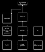
Max038
The MAX038 has a phase–lock function, with a variable duty cycle square wave output (=PWM).
Adding this wave shaping feature to the TC resonator could improve efficiency.
Adding phase control could be another nice feature.
Only how to make this right
The MAX038 has a phase–lock function, with a variable duty cycle square wave output (=PWM).
Adding this wave shaping feature to the TC resonator could improve efficiency.
Adding phase control could be another nice feature.
Only how to make this right
Attachments
Re: Max038
Hmm, I may have to use the tesla coil method instead, transformers are expensive
I still want to test with a cheapo transformer though... I think my father probably has some old P-P output transformers somewhere...
Good luck I hope it works!
Indalhc said:
With two "M399 ESL step-up transformer 125:1 turns ratio each $125.00" a 80 Volts peak input would give 20 kV. Not precisely cheap, and the low frequency response is not given (most people add dynamic subs to their ESLs...).
Hmm, I may have to use the tesla coil method instead, transformers are expensive
I still want to test with a cheapo transformer though... I think my father probably has some old P-P output transformers somewhere...
Indalhc said:Only how to make this right
Good luck
I hope it works!The early prototypes
Thanks man
Phase control on the resonator could by the way be like playing tennis, knowing exactly when to hit the ball (Not that I know very much about the sport).
Good luck to you also with those transformers! I expect to be getting there one day myself eventually (for the modulated grid version).
bigwill said:
Hmm, I may have to use the tesla coil method instead, transformers are expensive
I still want to test with a cheapo transformer though... I think my father probably has some old P-P output transformers somewhere...
Good luck
Thanks man
Phase control on the resonator could by the way be like playing tennis, knowing exactly when to hit the ball (Not that I know very much about the sport).
Good luck to you also with those transformers! I expect to be getting there one day myself eventually (for the modulated grid version).
- Status
- This old topic is closed. If you want to reopen this topic, contact a moderator using the "Report Post" button.
- Home
- Loudspeakers
- Planars & Exotics
- 'Biefeld-Brown effect' based full range drivers