Calvin said:Hi,
just connct several 1kV-Diodes in series, eg. 1N400x
jauu
Calvin
Hi
These CCFL inverters run at between 40 and 100 KHz so you can't use rectifiers normally used at 50/60 Hz - they will self destruct. You must use fast recovery diodes such as are found in the line output stages of TV sets. Typical part numbers are BY359-1500, FR307, BY228 etc.
If you want more voltage, use a Cockroft-Walton voltage multiplier. There's a good explanation of them here.
http://home.earthlink.net/~jimlux/hv/cw1.htm
An easier way may be to get hold of a corona power supply unit from a junked photocopier. These typically put out from 3 to 7Kv DC and are usually adjustable over a small range. Their drawback is that they often run off 24 volts DC.
As always, take extreme care - this stuff bites hard.
If you're not confident, don't try it.
Cheers
Rob
Hi,
This link shows the same :
http://hyperphysics.phy-astr.gsu.edu/HBASE/electronic/voldoub.html
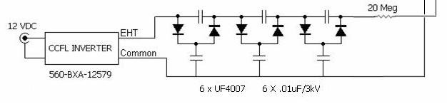
For higher voltage , you simply take a voltage quadrupler and extend it with as many stages as you need.
Note that you don't need caps and diodes rated at full output voltage , only around 2x your peak input voltage.
Add a 20Meg resistors at output. Use many resistors in series(10-15) , because standard carbon films are usually rated at only 200-400V.
Lukas.
This link shows the same :
http://hyperphysics.phy-astr.gsu.edu/HBASE/electronic/voldoub.html
For higher voltage , you simply take a voltage quadrupler and extend it with as many stages as you need.
Note that you don't need caps and diodes rated at full output voltage , only around 2x your peak input voltage.
Add a 20Meg resistors at output. Use many resistors in series(10-15) , because standard carbon films are usually rated at only 200-400V.
Lukas.
CCFL inverter help please?
Could someone help me figure out what I’m doing wrong? I purchased a few of the CCFL inverters and some 24 VDC power supplies to make ESL bias supplies, but I’m having trouble rectifying the inverter’s output.
I’m using a 100X ‘scope probe to monitor what I’m doing. The inverter by itself (no load or rectifier on its output) seems to work as expected; I see a 3.2 KV peak to peak, 30 KHz sine wave at the inverter’s output, relative to the inverter’s ground. When I try to rectify that signal I run into trouble.
I’ve tried a single FR307 diode and 300 pF capacitor , wired as suggested by I_F in post #6, but I see only AC at the junction between the diode and capacitor. Thinking that the 1 KV rating on the diode meant that it might be unhappy, I wired four fresh ones in series and used them in place of the single. Still no DC; just a reduced amplitude sine wave at the diode-capacitor junction.
The only DC I’ve seen is when I tried making a voltage divider out of 33 Mohm and 1 Mohm resistors ( 1 Mohm on the ground side) and used the junction between them as the connection point for the diode. I then saw a 10 volt DC offset with a few volts of ripple on top of it.
I’m not feeling very bright at the moment, so I’m swallowing my pride and revealing my ignorance. Can anyone point me in the right direction? I’d be very appreciative!
Few
Just a quck follow-up to my own email: I was wondering whether the CCFL unit was actually working fine but my test set-up was misleading me so I replaced the CCFL unit with a lab high voltage supply. The ESL worked fine that way so I guess my CCFL inverter plus rectifier circuit truly is malfunctioning.
Also, I wanted to clarify that my use of the voltage divider (as described in my last post) was merely to see if I could diagnose the source of my troubles. I thought the full voltage out of the inverter might have been causing misbehavior so I tried to take it down a notch with the voltage divider.
Anyway, I'm still interested in any advice or suggestions anyone has to offer.
Thanks in advance,
Few
The inverter probably produces HV AC by use of resonance in a small ferrite core transformer. Putting a 300 pF cap on it directly will move the resonance far away from the operating frequency and reslut in low output.
Try putting a large resistor inseries with the 300 pF cap (try 20M or so). It will take the cap a while to charge, but it may solve your problem.
I_F
Try putting a large resistor inseries with the 300 pF cap (try 20M or so). It will take the cap a while to charge, but it may solve your problem.
I_F
Thanks very much for the reply, I_F. I believe you're exactly right about the mode of operation of the inverter; it is based on a resonance involving a small transformer. I'm not sure the loads I've used have altered the frequency of operation, though. I'll take a closer look with that in mind to verify. Also, there are already two capacitors on the inverter's circuit board, located between the transformer and the two output leads.
I've tried putting a 1 Mohm resistor in series with the capacitor, as you suggested, but still see a somewhat distorted sinewave with no DC offset between the diode and the capacitor. I've not yet tried a larger resistor, but will do so.
In the meantime, if anyone else has comments or suggestions to offer, I'm still interested in as many ideas as I can accumulate.
Few
Thanks for the suggestion.
Does anyone know whether I should be tapping into the output of the CCFL inverter before or after the integral capacitors that are connected to the transformer's secondary? On a related note, there are two such capacitors, one for each of the two outputs. I've been working under the assumption that the two capacitors are identical and that the two outputs are identical as well, since they seem to originate at the same point in the circuit. If that's a mistake, please let me know.
Does anyone know whether I should be tapping into the output of the CCFL inverter before or after the integral capacitors that are connected to the transformer's secondary? On a related note, there are two such capacitors, one for each of the two outputs. I've been working under the assumption that the two capacitors are identical and that the two outputs are identical as well, since they seem to originate at the same point in the circuit. If that's a mistake, please let me know.
I don't have a schematic from the manufacturer, so I've made an attempt to trace out what's going on. If something simply doesn't make sense, please let me know. I'll be surprised if I didn't introduce at least one mistake.
schematic
The components within the dashed box on the left represent one attempt I made to rectify the output. There are a multitude of connections on the transformer's primary side, so I just used the numbering scheme as it's printed on the PCB. Finally, note that the 24 VDC input is on the right, and the high voltage AC output is on the left. Here's what the board looks like from the component side, in case it helps.
Top View
As always, thanks for the help.
That's what I was going to say, but when I measured it to double check, I had a hard time rationalizing the results. I thought I could get away with measuring the capacitance as long as one of the two capacitor leads was disconnected from the circuit, but I guess I was wrong.
The minimal info I can find on that particular inverter say it produces 1000Vrms. ccfl inverters can usually supply 3-5 mA out, though at a voltage a little lower than the open circuit (start-up) voltage value. Your rectifier circuit should charge the 300 pF cap to about -750VDC relative to ground. 750V bias won't make a sensitive ESL- maybe the output is low and you are not hearing it due to the low bias voltage.
When you connect a scope probe to the circuit if you connect directly across the 300 pF cap the probe's voltage divider is going to load the cap and discharge it. What is the scope probe's divider resistance? It doesn't take much to discharge a 300 pF cap. You may be charging and discharging the cap on each cycle, hence the AC that you see on the scope. What frequency is the waveform on the scope?
Another possibility is that your scope ground may be loading the 24V supply and killing the 24V going into the inverter. Check the input voltage while you are making the output measurement.
I_F
- Status
- This old topic is closed. If you want to reopen this topic, contact a moderator using the "Report Post" button.
- Home
- Loudspeakers
- Planars & Exotics
- low cost, small, safe bias supply