I'll have to look that one up, the variation used in the paper only contains height (h), distance to the listener (r), and D/S spacing (d):
P = I(signal) * V(pol) / (2 Pi d h sqrt(c r f) )
hi,
With sqrt(f) in the denominator, this tells you that with constant current fed to an ESL line source the SPL will fall -3dB/octave as frequency increases. Note also that sqrt(r) is in the denominator so response falls -3dB for each doubling of distance from the line source; a well known phenomenon.
But, we usually think in terms of applied voltage since our amplifiers and step-up transformers are good approximations of voltages sources. Take a look at equation (5) from the paper where the Walker type equation is converted to Vsignal instead of Isignal:
P=V(signal)*V(pol)*C*sqrt(f) / (d*h*sqrt(c*r))
Now sqrt(f) is in the numerator. So, with constant voltage fed to an ESL line the response will rise +3dB/octave with increasing frequency. This implicitly takes care of the dipole roll-off for low frequencies and directivity factor for high frequencies. This rise is exactly what the R-C transmission line is use to equalize out.
For derivition and discussion of point source and line source Walker equations, see sections 3.3.2 and 3.3.11 of Baxandall's ESL chapter in the book "Loudspeaker and Headphone Handbook".
Last edited:
I think kavermei already addressed this question, but I thought I'd add a few comments. Yes, 4 sections is all that is needed to achieve flat on-axis response from 300hz - 20kHz. But, like you said, if you want to use a minimum section width of 1/2" and only 4 sections, you won't have much panel area, so your ESL won't be very loud.
According to the paper, 10mm strips give you the following SPL attenuation at + and - 80 degrees off-axis:
5kHz -> -0.2dB
10kHz -> -1.2dB
20kHz -> -5.5dB
30mm strips make that:
5kHz -> -2.8dB
10kHz -> -16.3dB
20kHz -> zero at 35 degrees (due to phase reversal) with lobes at + and - 60 degrees
When designing a panel, I'd suggest starting out by:
1) defining the largest panel(height & width) you can live with. This will give you the highest sensitivity and maxSPL.
2) Then, pick your LF breakpoint. With area already defined in 1), this also sets the max SPL for your design.
3) Figure how many sections you need to reach beyond 20kHz.
4) If your sections are already 1/2" or whatever you deem "small enough" then you are done. Otherwise, increase the number of sections until you get there. Your high frequency extension will be much higher then needed, but the leakage inductance of your transformer will most likely cut of the HF response at not much higher than 20kHz.
Yeah I agree with this recipe, except the last statement about the transformer -- use toroids and you'll easily get way more than 20kHz. 50-100kHz more likely.
Also for completeness max SPL is also determined by D/S spacing (but that is in turn determined by the LF breakpoint) and by Vpol (which is limited by the quality of your isolation).
Another option is to only use the "small enough" section width on the first few sections of the transmission line and then increase the size of the section after that. If you look at the frequencies fed to each section you can see that as you travel down the line you pretty quickly lose the highs that would cause beaming problems. You just need to adjust the size of the transmission line resistors when you reach these sections.
I think this will worsen the polar response higher up off-axis. It's probably okay when you're more or less in the sweet spot. BTW that's how my current ESL is built
")
I'll be back to work on Tuesday, and should be able to post the spreadsheet for you to experiment with then.
Thanks, could be interesting to have.
Kenneth
Also for completeness max SPL is also determined by D/S spacing (but that is in turn determined by the LF breakpoint) and by Vpol (which is limited by the quality of your isolation).
Hello again
According to the Baxandall ESL paper and my experiments, contrary to popular belief D/S spacing does not come in to play when defining max SPL. It only places a limit on how low in frequency you can put out that max SPL due to the physical constraints of diaphragm motion.
The two parameters that define max SPL for an ESL are 1) area 2) breakdown voltage gradient for air. See section 3.3.9 of Baxandall chapter.
For a given D/S there are particular values of Vbias and Vsignal based on the breakdown voltage gradient which will produce maxSPL.
See section 3.2.9 of Baxandall chapter.
With the area of an ESL held constant, if you double the D/S you double the required Vbias and Vsignal required to reach that same value of max SPL. However, with double the D/S the voltage gradient in the airgap is the same.
Of course, that is theory....which I love!
In practice, the higher Vsignal must be generated by a transformer with twice the step-up ratio which may place limits on the bandwidth over which you can reach that SPL. Also, as you mentioned, higher voltages may be limited by imperfect stator insulation, or sharp edges and/or dust in the air gap.
I think this will worsen the polar response higher up off-axis. It's probably okay when you're more or less in the sweet spot. BTW that's how my current ESL is built
Of course this is true. My point was that if he wanted to get some benefits of the narrow sections without using them over the whole panel, put them at the beginning of the line where the most high frequencies are.
Hi there,
Ermm, yes you are right! I knew that, since I have read Baxandall's book chapter, but it somehow slipped my mind this morning My mistake.
This thread got me thinking. For some reason we European DIYers build mostly wire stators. Now it would be very easy to bring out every single wire as a separate signal once the wires have been glued down. If I ever build another panel I will definitely do that. This'll result in very narrow sections 3...5mm and should give superior dispersion.
When I built my current panels as a young and reckless man (that was 6 years ago) I lacked the foresight to make the stators separable, so I'm kinda stuck now to my 25mm center section surrounded by 3 big sections of about 70mm. As you would expect, it's pretty beamy but in the sweet spot it's, well, sweet!
Kenneth
Hello again
According to the Baxandall ESL paper and my experiments, contrary to popular belief D/S spacing does not come in to play when defining max SPL. It only places a limit on how low in frequency you can put out that max SPL due to the physical constraints of diaphragm motion.
Ermm, yes you are right! I knew that, since I have read Baxandall's book chapter, but it somehow slipped my mind this morning
My mistake.This thread got me thinking. For some reason we European DIYers build mostly wire stators. Now it would be very easy to bring out every single wire as a separate signal once the wires have been glued down. If I ever build another panel I will definitely do that. This'll result in very narrow sections 3...5mm and should give superior dispersion.
When I built my current panels as a young and reckless man (that was 6 years ago) I lacked the foresight to make the stators separable, so I'm kinda stuck now to my 25mm center section surrounded by 3 big sections of about 70mm. As you would expect, it's pretty beamy but in the sweet spot it's, well, sweet!
Kenneth
Great info guys.
Can't wait to see your spread sheet program,Steve.
After I get caught up in my things that have to get done now list,I will be able to start a new set of panels, as I have just bought all of the materials to do so.
With my method of construction ,this could very easly be applied.
My little panels are only 85mm wide and do get quite loud down to 300hz in a nearfield configuration.
I had thought about taking a few swipes with a dremel tool to segment the stators ,but I'm sure this would prove difficult to reseal the edges to stop the arcing.
A new panel build would take as much or less time to make, while not having more than needed sharp edges to contend with.
I would like try this method as I don't particularly care for the beaming effect as well, either.
So it will be interesting to compare two sets of panels of identical size and exprience the effect.
From everthing I have read that segmented stators are the way to go if done properly. jer
Hi again,
Exactly! Looks like the RC line is the ideal partner for a voltage source.
In The Netherlands there's a guy who took the other approach: no segmentation but using an amplifier which acts much more like a current source. (The fact that it was a direct drive amp helped in the realization of such a behavior). Check it out here:
Elektrostatic Loudspeakers - Frank Verwaal
NOT the approach I would take, but there's a wealth of information on that site.
Oh and here's an online simulator which can be useful:
Electrostatic Loudspeaker (ESL) Simulator
Kenneth
But, we usually think in terms of applied voltage since our amplifiers and step-up transformers are good approximations of voltages sources. Take a look at equation (5) from the paper where the Walker type equation is converted to Vsignal instead of Isignal:
P=V(signal)*V(pol)*C*sqrt(f) / (d*h*sqrt(c*r))
Now sqrt(f) is in the numerator. So, with constant voltage fed to an ESL line the response will rise +3dB/octave with increasing frequency. This implicitly takes care of the dipole roll-off for low frequencies and directivity factor for high frequencies. This rise is exactly what the R-C transmission line is use to equalize out.
Exactly! Looks like the RC line is the ideal partner for a voltage source.
In The Netherlands there's a guy who took the other approach: no segmentation but using an amplifier which acts much more like a current source. (The fact that it was a direct drive amp helped in the realization of such a behavior). Check it out here:
Elektrostatic Loudspeakers - Frank Verwaal
NOT the approach I would take, but there's a wealth of information on that site.
Oh and here's an online simulator which can be useful:
Electrostatic Loudspeaker (ESL) Simulator
Kenneth
ESL Line Source XL Spreadsheet Calculator
Here is the XL spreadsheet.
I appologize for the mixing of units, but at least I labeled them.
I tried to list all the assumptions and equations on the "Notes" & "Directions" tab, but may have missed some.
Let me know if you notice something missing or the directions don't make sense.
A few observations:
1) Native response of floor to ceiling ESL is sloped +3dB with increasing frequency
2) maxSPL increases linearly with Panel width.
2) maxSPL does not change with height of line source. (for more details see the "Notes" tab)
3) maxSPL decreases -3dB for each doubling of the listening distance.
4) maxSPL is NOT dependent on diaphragm to stator spacing, although the required Vsig & Vpol required to achieve it increase linearly with D/S.
Note that this does not mean that you can use whatever spacing you want to go as low as you want.
The spacing still must be defined to allow the required diaphragm motion for maxSPL at the LF breakpoint.
5) If you want to go low by setting the LF breakpoint low, efficiency suffers unless you increase panel width to compensate.
If you want it loud, make it a hybrid.
If you want it loud and low and don't want a hybrid, make it wide.
Enjoy.
Attachments
Let me know if you notice something missing or the directions don't make sense.
A couple people have asked how to get from the calculated sound pressure in (N/m^2) from the Walker equations to SPL.
I missed getting that put on the "Notes" tab.
From the book "Acoustics" by Beranek, equation (1.18):
SPL(dB) = 20*LOG(P/Pref)
where:
P = sound pressure (N/m^2)
Pref = reference sound pressure = 0.00002 (N/m^2)
From what I understand, SPL is an RMS value and the sound pressure values calculated from the Walker equations are peak pressures.
So, I multiplied the pressures values coming from the Walker equation by 0.7071 before calculating SPL.
Last edited:
There have been measurements of mid-sized flat panels which showed amplitude deviations of ~10dB within just 1° change of listening position.
That is certainly non-practical.
Here's a plot of my 16" x 46" active area single panel ESL as a function of listening angle (polar response). I get about a 10dB drop in 5 degrees. It's a little odd to me that the higher frequencies do not drop, I'm thinking that it might be the diffraction through the perf-metal.
http://quadesl.com/speaker/diyesl/polar_fine.gif
It's not practical for a casual listening speaker, but for a single person ride, it's not bad.
Sheldon
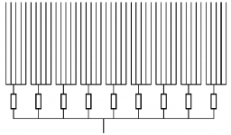
In Frank Verwaal papers there is a table (Part #2 p.80) with the RC filters to be used for linear frequency response. Next figures show the implementation of the idea.
So, am I right, assuming:
1) for different stip widths the table and individual resistors per stip (Fig.#1) is applicable.
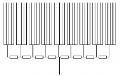
2) if the ladder structure is employed (Fig.#2) then all the resistors are equal, strip width are all the same and bolsert's spreadheet is applicable, as well as the AES article we discussed.
Alex
So, am I right, assuming:
1) for different stip widths the table and individual resistors per stip (Fig.#1) is applicable.
2) if the ladder structure is employed (Fig.#2) then all the resistors are equal, strip width are all the same and bolsert's spreadheet is applicable, as well as the AES article we discussed.
Alex
Attachments
In Frank Verwaal papers there is a table (Part #2 p.80) with the RC filters to be used for linear frequency response. Next figures show the implementation of the idea.
So, am I right, assuming:
1) for different stip widths the table and individual resistors per stip (Fig.#1) is applicable.
2) if the ladder structure is employed (Fig.#2) then all the resistors are equal, strip width are all the same and bolsert's spreadheet is applicable, as well as the AES article we discussed.
Hello Alexberg,
If you use individual resistors to feed each strip (Fig. #1) you will need increasing resistor values for each section to obtain a flat response. The resistor values shown in Frank's table are specific to his design. ie number and size of each segment, capacitance of each segment, target bandwidth for flat response.
As kavermei already mentioned, the ladder network (Fig. #2) with equal sectional widths and resistors is similar to the symmetric layout analyzed in the AES paper. All that is missing is the initial feed resistor.
The spreadsheet gives values for the asymmetric layout which the AES paper uses when deriving most of the equations. I modified your (Fig. #2) to show what feed layout should be used for the section sizes and feed resistances(R) calculated in the spreadsheet. I now realize I should have included it in the spreadsheet documentation since not everybody who uses the spreadsheet will have a copy of the AES reference paper.
Note that the resistor feeding the first section is half the value of the rest of the resistors in the ladder network. In practice, this resistor can be put on the primary side of the transformer where it can also help with saturation control. Just take the value (R/2) and divide by the square of the step-up ratio. Be advised that you will probably have to tweak the value of this first resistor to compensate for other factors not considered in the HF response as mentioned on the directions tab of the spreadsheet.
3) Transformer leakage inductance behavior at HF is ignored
4) Section to section capacitive coupling is ignored
5) HF loss due to the inertia of the diaphragm and/or the inertia of air in the holes in the stators is ignored.
If anybody is interested, I can post the ratios or factors to apply to the spreadsheet values for feed resistance and sectional capacitance if you want to use a symmetric layout. Let me know. Or, perhaps, a version 2 of the spreadsheet with separate tabs for symmetric and asymmetric configurations.
Attachments
If anybody is interested, I can post the ratios or factors to apply to the spreadsheet values for feed resistance and sectional capacitance if you want to use a symmetric layout. Let me know.
I'm planning on a symmetric layout so a spreadsheet version for that would be great! Thanks for the generous offer.
Few
Hi,
I would argue that it should be kept in the secondary circuit, since in the primary it will cause distortion.
I think it's better to control saturation by using a line-level highpass filter.
Kenneth
[...]In practice, this resistor can be put on the primary side of the transformer where it can also help with saturation control. Just take the value (R/2) and divide by the square of the step-up ratio.[...]
I would argue that it should be kept in the secondary circuit, since in the primary it will cause distortion.
I think it's better to control saturation by using a line-level highpass filter.
Kenneth
Having now owned Quad ESL 57's and Quad ESL 63's I have to say quads combination of filter and delay line in the ESL 63 is very impressive, for improving the treble dispersion. Unless you play with a pair of ESL 63's for a while you would not realize how good they are at treble dispersion because the bass is still very directive.
Originally Posted by bolserst
[...]In practice, this resistor can be put on the primary side of the transformer where it can also help with saturation control. Just take the value (R/2) and divide by the square of the step-up ratio.[...]
Hi,
I would argue that it should be kept in the secondary circuit, since in the primary it will cause distortion.
I think it's better to control saturation by using a line-level highpass filter.
Kenneth
I agree, from a distortion standpoint you want to minimize the resistance in the primary circuit. For practical reasons, I usually keep a small primary series resistance to protect the amplifier just in case something unexpected happens or the filter network is accidently bypassed. Any additional resistance needed is put in the secondary circuit. I found that as long as the primary series resistance is < 2ohm the distortion increase is pretty minimal for typical M6 core material.
The reason I mentioned it was to point out that even if the first feed resistor doesn't seem to be in the circuit(on the secondary side connected to the first section) it might have been moved to the primary side where its function is not as obvious.
For those unfamiliar with the source of distortion kavermei is talking about, this post explains it a bit more.
http://www.diyaudio.com/forums/planars-exotics/161485-step-up-transformer-design-22.html#post2194792
Also, for a visual aid, geraldfryjr had posted some plots showing the input voltage and distorted current waveforms for the primary circuit.
http://www.diyaudio.com/forums/planars-exotics/161485-step-up-transformer-design-22.html#post2194033
Last edited:
I'm planning on a symmetric layout so a spreadsheet version for that would be great!
I should have time to post an updated spreadsheet in a few days which includes the symmetric layout.
- Status
- This old topic is closed. If you want to reopen this topic, contact a moderator using the "Report Post" button.
- Home
- Loudspeakers
- Planars & Exotics
- experiences with ESL directivity?