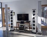
Way back in 2010 I started a project that has finally made its way into my living room. It started as a vertical array of open baffle woofers to go with a new wire-stator electrostatic loudspeaker (ESL). The early stages of the woofer baffle construction were posted here. Alas, the photo links are now broken. In the end I switched to making my own planar magnetic drivers instead of finishing the ESLs.
In the middle of it all my wife and I had a new house designed and built. Somehow the speakers have taken longer to build than our house.
And of course they're still not done. I'm using a miniDSP OpenDRC-DA8 for the crossovers and equalization. I'm new to that game so I think I'll try to get my act together a bit more before posting details on that part of the project. I have made some progress getting a reasonably flat on-axis response but haven't checked on polar responses, tweaked crossovers, or tried FIR filters to fix the phase. Lots left to be done.
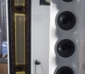
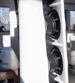
The woofers are Dayton 8" reference series from parts express. They're gripped by their magnets rather than by attaching their fronts to the baffle (see the second photo below). The baffle was made with kerfed MDF that want bent into a curve. MDF disks were glued to the front, and then fiberglass and epoxy formed the curved surfaces. The rear spine to which the woofers are mounted was made with laminated fir, half of a PVC pipe to form a round counter, and again fiberglass epoxied around the whole mess to smooth the curves and hold the PVC in place.
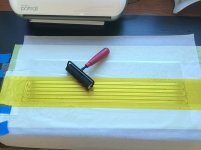
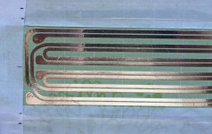
The planar magnetic drivers consist of two 10 micron thick aluminum traces, one that covers most of the diaphragm, and a narrow central one that I'm hoping to use as a sort of tweeter. I say sort of because to start I'll run everything from about 150 Hz to 20 kHz through the tweeter, and run 150 Hz - 2 kHz (or something like that---still to be determined) through the wider pattern that surrounds the "tweeter." The aluminum is on 13 micron thick kapton tape and the edges of the kapton have thin stretch wrap material to serve as a sort of surround. The stretch wrap is mounted to the frames that are made of garolite from McMaster-Carr (it's a phenolic material).
The planar magnetic drivers are single-sided, with 42-grade NdFeB magnets glued with cyanoacrylate (Crazy glue) on to perforated steel sheets. Each magnet is 1" long, 0.25" wide, and 0.125" thick. The poles are the 1" x 0.25" faces.
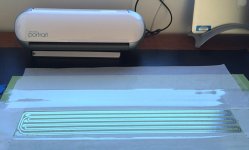
I cut the aluminum traces using a Silhouette Portrait computer controlled cutter that I learned about on diyaudio. A thousand thanks to Bandsei for helping me get started on that and coming up with useful 10 micron aluminum-paper laminate.
The somewhat crazy dimensions of the planar magnetic towers evolved from 1) wanting tall line arrays because my living room, dining room, and kitchen are in a very long open space and I wanted decent sound throughout (without blasting someone sitting close to the speakers) and 2) mission creep set in as I assembled the drivers and then built the frame that houses them. I actually intended to end up with something at least a foot shorter but that's what happens when you design as you build, I guess.
I'll post some measurements once I make a bit more progress.
Few
P.S. Moderators: I actually intended to post this in the "planar and exotic" forum because of the diy planar magnetic component. The OB woofer project was first posted here but feel free to move this post if it would make more sense elsewhere.
In the middle of it all my wife and I had a new house designed and built. Somehow the speakers have taken longer to build than our house.
And of course they're still not done. I'm using a miniDSP OpenDRC-DA8 for the crossovers and equalization. I'm new to that game so I think I'll try to get my act together a bit more before posting details on that part of the project. I have made some progress getting a reasonably flat on-axis response but haven't checked on polar responses, tweaked crossovers, or tried FIR filters to fix the phase. Lots left to be done.
The woofers are Dayton 8" reference series from parts express. They're gripped by their magnets rather than by attaching their fronts to the baffle (see the second photo below). The baffle was made with kerfed MDF that want bent into a curve. MDF disks were glued to the front, and then fiberglass and epoxy formed the curved surfaces. The rear spine to which the woofers are mounted was made with laminated fir, half of a PVC pipe to form a round counter, and again fiberglass epoxied around the whole mess to smooth the curves and hold the PVC in place.
The planar magnetic drivers consist of two 10 micron thick aluminum traces, one that covers most of the diaphragm, and a narrow central one that I'm hoping to use as a sort of tweeter. I say sort of because to start I'll run everything from about 150 Hz to 20 kHz through the tweeter, and run 150 Hz - 2 kHz (or something like that---still to be determined) through the wider pattern that surrounds the "tweeter." The aluminum is on 13 micron thick kapton tape and the edges of the kapton have thin stretch wrap material to serve as a sort of surround. The stretch wrap is mounted to the frames that are made of garolite from McMaster-Carr (it's a phenolic material).
The planar magnetic drivers are single-sided, with 42-grade NdFeB magnets glued with cyanoacrylate (Crazy glue) on to perforated steel sheets. Each magnet is 1" long, 0.25" wide, and 0.125" thick. The poles are the 1" x 0.25" faces.
I cut the aluminum traces using a Silhouette Portrait computer controlled cutter that I learned about on diyaudio. A thousand thanks to Bandsei for helping me get started on that and coming up with useful 10 micron aluminum-paper laminate.
The somewhat crazy dimensions of the planar magnetic towers evolved from 1) wanting tall line arrays because my living room, dining room, and kitchen are in a very long open space and I wanted decent sound throughout (without blasting someone sitting close to the speakers) and 2) mission creep set in as I assembled the drivers and then built the frame that houses them. I actually intended to end up with something at least a foot shorter but that's what happens when you design as you build, I guess.
I'll post some measurements once I make a bit more progress.
Few
P.S. Moderators: I actually intended to post this in the "planar and exotic" forum because of the diy planar magnetic component. The OB woofer project was first posted here but feel free to move this post if it would make more sense elsewhere.
Attachments
-
 PC210113 speaker portrait in sun.jpg132.4 KB · Views: 3,049
 -
 Kapton on traces.jpg107.3 KB · Views: 1,597
 -
 close-up of planar traces.jpg139.8 KB · Views: 2,817
 -
 planar trace with Silhouette.jpg86.7 KB · Views: 2,917
 -
 PC210110 grill off planar.jpg135.8 KB · Views: 2,917
 -
 OB rear view.jpg129.2 KB · Views: 2,970
Last edited:
Beautiful indeed! I have a physics question. Usually with a di-pole you must keep the baffle width wide enough to prevent front to back cancellation. This doesn't seem to be a concern for you? At 150 Hz the wavelength is around 7', so I would expect the PM drivers to be radiating omnidirectionally, and therefore cancel considerably more than with a wide baffle.
Best,
Erik
Best,
Erik
Thanks for the kind words, all. I think I spent as much time painting and sanding as I did making the planar drivers. I've decided I do NOT have a future career as a painter.
Erik: Yes there definitely is front-to-back cancellation. I'm using the miniDSP to equalize the response and compensate for that effect, while also providing the crossovers.
Few
Erik: Yes there definitely is front-to-back cancellation. I'm using the miniDSP to equalize the response and compensate for that effect, while also providing the crossovers.
Few
Thanks Mark. I made some measurements in my shop as I was testing ideas but there wasn't enough room to allow much reflection-free time for the measurements. I've got more room now that the speakers are in their final-ish locations (they'll be pulled away from the rear wall for more serious listening). I've done some rough measurements just so I could get the miniDSP up and running and yielding a reasonably flat response at the main listening seat but they're not worth posting yet. I do plan to do some more systematic measurements and I'll share them as I make them. I need to learn the art of measuring tall dipoles in a highly reflective environment. I'm open to suggestions!
Part of my intent when designing the speakers was to reduce floor and ceiling reflections by making the speakers tall. I'm also hoping I can aim the dipole null at the wall of windows that's just to the left of the speakers and reduce the impact of that first side reflection. I guess we'll see how that all works out.
Thanks for your interest.
Few
What software are you using for measurement?
For raw frequency response you could do near field measurements. About 6 mm away from the diaphragm. But you will have to hunt across the diaphragm both on the vertical and the horizontal planes to find the best response. This will give you almost as good as anechoic measurements.
Then if you want listening position measurements you can have a reference against the near field to see what is getting messed up by reflections.
Erik,
As you know doubt learned from your reading, there's a lot of cancellation at low frequencies, just as your intuition would suggest. Fortunately, if your drivers can move enough air then equalizing the dipole cancellation is viable. The six 8" woofers in my OB panels have about the same surface area as a 19" woofer. On the other hand, my narrow baffle raises the frequency at which the cancellation begins, and the 8" woofers have less maximum excursion than would a typical very large woofer. So far, even with the bass flattened down to the low 30's Hz I've not seen large demands on woofer excursion when listening to jazz and classical music (no low frequency organ blasts yet). I have a pair of old NHT 12" woofers I can put into sealed boxes if I find I'm really missing something in the bottom octave. I'd rather not add two large sealed boxes to the rather large speakers my wife just accepted into her living room, though.
Thanks for the nearfield suggestion, Mark. I did just that with the woofers and of course got a very clean result. In the limited time I had I couldn't figure out a convenient way to use the nearfield measurement to compute what the response would be with the dipole cancellation included. John Kreskovsky suggests a method (invert and delay the response and add it to the main signal) but I couldn't figure out how to implement it just using Room Eq Wizard. With more time I can measure an impulse response and import it into Matlab where I have more control. I've also downloaded rePhase but I haven't worked with it yet so I don't have a good sense of its capabilities. I plan to use rePhase to figure out how to fix the phase response once I get the magnitudes worked out.
I haven't taken a nearfield measurement of the planar magnetic drivers yet but it's certainly worth doing. Thanks for the suggestion.
Few
Hi Few,
While I have never done an OB design before, I have followed them off and on. The closest I've seen to your designs is something like the Infinity arrays, which used very wide or U shaped baffles to reduce the cancellation effects. I'll go and see if I can find some models, it could be fun.
A good book on measurements is D'Appolito's Testing Loudspeakers.
Best,
Erik
I've done some gated measurements, and tried a quick attempt at a ground plane measurement. I had high hopes for the ground plane but my first attempt didn't inspire much confidence. The trick, of course, is not just choosing the result that looks prettiest but instead finding the measurements that provide the most useful information. I'm still on that quest.
I have d'Appolito's book and have reviewed it a bit recently but really should give it a closer look now that I'm making measurements. One of the questions is how far away to place the mic when the speaker is 8 feet tall, and standing on a concrete floor (acoustic mirror). The response varies with distance, of course. Probably I need to go through the trouble of moving the speaker into the middle of the room and placing the mic equidistant between the floor and ceiling to try to squeeze as much reflection-free time as I can muster so that gating doesn't kill my measurement bandwidth.
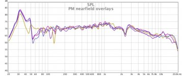
In the meantime I'm attaching some nearfield results. The planar magnetic (PM) results are the result of a few different mic positions in front of the diaphragm, and one where I've changed the position of the speaker in the room because when I looked at the impulse response I found the back wave reflected from the rear wall was coming through rather strongly, even with the nearfield measurement approach. There were no crossovers and there was no equalization applied but I used 1/24 octave smoothing. Both the front and rear grills were in place so I'm measuring through the cloth. No doubt I'm losing a bit of high frequency response as a result but there is a roll-off even without the grills. Also, I'm using an old Behringer ECM8000 mic and haven't yet loaded any calibration files into the machine I'm using for measurements. That'll affect the high frequency response a bit as well.
I'm also attaching a single measurement from just in front of one of the open baffle (OB) woofers. Ignore differences between absolute levels---the gain settings were different when I measured the PM and OB speakers.
MODERATORS: Should I post a message in the planar forum to alert those readers about this planar magnetic discussion? Do you want to move the whole thread?
Few
I have d'Appolito's book and have reviewed it a bit recently but really should give it a closer look now that I'm making measurements. One of the questions is how far away to place the mic when the speaker is 8 feet tall, and standing on a concrete floor (acoustic mirror). The response varies with distance, of course. Probably I need to go through the trouble of moving the speaker into the middle of the room and placing the mic equidistant between the floor and ceiling to try to squeeze as much reflection-free time as I can muster so that gating doesn't kill my measurement bandwidth.
In the meantime I'm attaching some nearfield results. The planar magnetic (PM) results are the result of a few different mic positions in front of the diaphragm, and one where I've changed the position of the speaker in the room because when I looked at the impulse response I found the back wave reflected from the rear wall was coming through rather strongly, even with the nearfield measurement approach. There were no crossovers and there was no equalization applied but I used 1/24 octave smoothing. Both the front and rear grills were in place so I'm measuring through the cloth. No doubt I'm losing a bit of high frequency response as a result but there is a roll-off even without the grills. Also, I'm using an old Behringer ECM8000 mic and haven't yet loaded any calibration files into the machine I'm using for measurements. That'll affect the high frequency response a bit as well.
I'm also attaching a single measurement from just in front of one of the open baffle (OB) woofers. Ignore differences between absolute levels---the gain settings were different when I measured the PM and OB speakers.
MODERATORS: Should I post a message in the planar forum to alert those readers about this planar magnetic discussion? Do you want to move the whole thread?
Few
Attachments
Awesome.
No smoothing.
Really good results.
What you see in marketing information is useless creative wishful hopes and dreams.
Learning to measure a dipole is jumping into the deep end of the pool.
Not easy even for me. Very dependant on reflections. And measuring without reflection doesn't characterize what you are hearing.
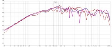
Here are some awkward attempts at gated measurements of the planar magnetic tower. They're all smoothed at 1/24 octave, and gated at 9 ms. I did add a 6 dB/octave high pass at 60 Hz to attenuate the fundamental resonance a little bit but otherwise there's no crossover or equalization applied.
The differences between measurements are just mic heights above the floor (ranging from about 3 to 5 feet). Mic to speaker distance is about 6 feet.
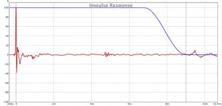
I'm attaching a typical impulse response so others can get a sense of what's included and excluded by the 9 ms window. The details of the undesirable squiggles within the first millisecond vary with mic position. I'm assuming they reflect differences in the interference pattern formed by the radiation from the different point on the speaker diaphragms. I could shorten the window and kill that 5 ms glitch but that really limits the resolution and bandwidth. I probably should find a good way to do some spatial averaging before figuring out what I should try to fix with the miniDSP.
Few
The differences between measurements are just mic heights above the floor (ranging from about 3 to 5 feet). Mic to speaker distance is about 6 feet.
I'm attaching a typical impulse response so others can get a sense of what's included and excluded by the 9 ms window. The details of the undesirable squiggles within the first millisecond vary with mic position. I'm assuming they reflect differences in the interference pattern formed by the radiation from the different point on the speaker diaphragms. I could shorten the window and kill that 5 ms glitch but that really limits the resolution and bandwidth. I probably should find a good way to do some spatial averaging before figuring out what I should try to fix with the miniDSP.
Few
Attachments
Well this is interesting...
I tried ground plane measurements again but they really got me nowhere, even if I tried to tilt the speaker to aim it at the mic laid on the floor.
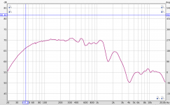
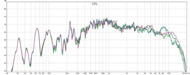
On a whim I moved the mic so that it's against one of the 8' tall windows that form one wall of the room. I wasn't seeing a ton of floor or ceiling bounce so I thought I'd try seeing if I could tame the first wall bounce by using the window as a vertical ground plane. The measurements below are all taken without any gating at all; just 1/24 octave smoothing and the same first order 60 Hz high pass to attenuate the fundamental resonance. The only differences are mic height, ranging from 3 to 5 feet.
Below about 400 Hz the room modes are very consistent and clear. And they can be measured with good resolution when there's no gating. Above that frequency the response is surprisingly reproducible and clean considering it was obtained in the world's most reflective listening room, without gating, and with the mic placed 11 feet from the speaker. Maybe the tall emitter really is doing a good job killing the floor and ceiling bounce?
Few
I tried ground plane measurements again but they really got me nowhere, even if I tried to tilt the speaker to aim it at the mic laid on the floor.
On a whim I moved the mic so that it's against one of the 8' tall windows that form one wall of the room. I wasn't seeing a ton of floor or ceiling bounce so I thought I'd try seeing if I could tame the first wall bounce by using the window as a vertical ground plane. The measurements below are all taken without any gating at all; just 1/24 octave smoothing and the same first order 60 Hz high pass to attenuate the fundamental resonance. The only differences are mic height, ranging from 3 to 5 feet.
Below about 400 Hz the room modes are very consistent and clear. And they can be measured with good resolution when there's no gating. Above that frequency the response is surprisingly reproducible and clean considering it was obtained in the world's most reflective listening room, without gating, and with the mic placed 11 feet from the speaker. Maybe the tall emitter really is doing a good job killing the floor and ceiling bounce?
Few
Attachments
Well this is interesting...
I tried ground plane measurements again but they really got me nowhere, even if I tried to tilt the speaker to aim it at the mic laid on the floor.
On a whim I moved the mic so that it's against one of the 8' tall windows that form one wall of the room. I wasn't seeing a ton of floor or ceiling bounce so I thought I'd try seeing if I could tame the first wall bounce by using the window as a vertical ground plane. The measurements below are all taken without any gating at all; just 1/24 octave smoothing and the same first order 60 Hz high pass to attenuate the fundamental resonance. The only differences are mic height, ranging from 3 to 5 feet.
Below about 400 Hz the room modes are very consistent and clear. And they can be measured with good resolution when there's no gating. Above that frequency the response is surprisingly reproducible and clean considering it was obtained in the world's most reflective listening room, without gating, and with the mic placed 11 feet from the speaker. Maybe the tall emitter really is doing a good job killing the floor and ceiling bounce?
Few
You will find that a tall array is better at masking the effects of boundary reflections. As in you will have opportunity to be in the area where the signal is coming from the speakers more than from reflections. Horns do that is another manner. They limit reflections.
A line array will have a greater power response if it is a true floor to ceiling array. The loss due to doubling of distance will be 3db per doubling of distance rather than 6db. As to moving your mic around and finding a better response. That is basically how it is done ! Especially with a planar is it difficult to get a smooth response without some tweaking.
I did days of testing AMT's last time I was in China and done outside or inside a 1 meter response was always raged. Many companies use a near field response that looks marvelous and "correct it" by drop the displayed SPL level and use this as a marketing method.
If you want a really good flat response of your planars you will need to be in the sweetest spot.
Regarding your ground plane measurement. Did you place your mic at 2 meters? And tilt your enclosure carefully? This will be useful more for a response test below 500 hertz. Above that it is not so easy to either reproduce the test nor is it really a real world listening condition test.
- Status
- This old topic is closed. If you want to reopen this topic, contact a moderator using the "Report Post" button.
- Home
- Loudspeakers
- Planars & Exotics
- DIY planar magnetic + open baffle woofer array