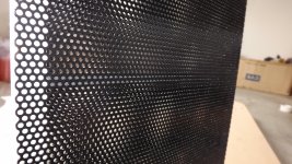
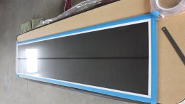
Well - Ive got 1250 x 300 1.2 mild steel stators painted , 6micron Dupont mylar , 4 x ( 2x6vac - 230vac ) toroids ,0.002mm 12mm copper tape , EHT supplies from ER Audio , and now just sourcing my 3mm VHN 3m Tape ( #4959 ) .
I was planning to space the 1220mm high with approx 3 horizontal spacers , 12mm x 3mm thick , almost ready to assemble and find out what happens.
I was planning to space the 1220mm high with approx 3 horizontal spacers , 12mm x 3mm thick , almost ready to assemble and find out what happens.
How thick is your paint coating?
I would suggest that it should be no thinner 8mil (.008").
You should try to achieve a thickness of about 10-12mil to be reliable from any arcing at all under normal mild condtions.
The voltages will be in the order of about 10Kv to 15Kv of swing from the setup transformers and and double that if they are pushed hard enough.
This is also good for use with bias voltages as high as 6Kv to 8Kv or so.
I typically used about 7Kv od bias on my little panels so you will have the advantage of more surface area and not have to run the bias that high.
Although 3mm D/S is quite large for a hybrid system, 2mm will be sufficient for as low as 200-300 hz with your section width of about <100mm.
Typically 1:100 D/S per width is the norm, But I have found that 1:50 gives adiquate spacing for the lower frequency's without loosing much effieciency for narrow width section's.
The more narrower the sections are the wider your HF dispersion will be.
I would say that 3" would be the least I would go, I have not ventured with dimensions less than 3" (3.25" actually) for a Hybrid midrange/tweeter useage.
jer")
I would suggest that it should be no thinner 8mil (.008").
You should try to achieve a thickness of about 10-12mil to be reliable from any arcing at all under normal mild condtions.
The voltages will be in the order of about 10Kv to 15Kv of swing from the setup transformers and and double that if they are pushed hard enough.
This is also good for use with bias voltages as high as 6Kv to 8Kv or so.
I typically used about 7Kv od bias on my little panels so you will have the advantage of more surface area and not have to run the bias that high.
Although 3mm D/S is quite large for a hybrid system, 2mm will be sufficient for as low as 200-300 hz with your section width of about <100mm.
Typically 1:100 D/S per width is the norm, But I have found that 1:50 gives adiquate spacing for the lower frequency's without loosing much effieciency for narrow width section's.
The more narrower the sections are the wider your HF dispersion will be.
I would say that 3" would be the least I would go, I have not ventured with dimensions less than 3" (3.25" actually) for a Hybrid midrange/tweeter useage.
jer
Last edited:
Hmmm - how to measure paint thickness ? - im just giving them a few coats of Black Epoxy Gloss Enamel . Another weekend gone and still watching the paint dry . - 16hrs minimum before next coat .
Im a bit unsure just how much to tension the mylar - 1.0 % or 1.5% ..or somewhere inbetween . - i understand the physics of going the light tension for resonance being lowered - but there must be much better performance for higher tension , as in quality of the bass . - we all know what wooly uncontrolled woffle sounds like. So im siding with the higher side for now - in the end , it will be like a baby - built with best intentions & breeding stock , but will be what it is once it pops out .
Im a bit unsure just how much to tension the mylar - 1.0 % or 1.5% ..or somewhere inbetween . - i understand the physics of going the light tension for resonance being lowered - but there must be much better performance for higher tension , as in quality of the bass . - we all know what wooly uncontrolled woffle sounds like. So im siding with the higher side for now - in the end , it will be like a baby - built with best intentions & breeding stock , but will be what it is once it pops out .
I use a Micrometer to measure it's thickness.
If you already have a base coat of black then use Clear to build up your thickness.
See this thread,
http://www.diyaudio.com/forums/plan...tric-coatings-fact-fiction-2.html#post2893839
I do hope that you used a primer as well.
For your section width your resonance should be in the range of 50hz to 100Hz depending on how high you set your tension.
I have found that having the resonance as high as 100hz is more annoying than it being in the 50Hz to 70Hz range.
I get 65-90hz with my 3.25" width and using only heat for tensioning using no mechincal methods at all.
Most likely you will be crossing over much higher than that anyhow.
Typically not lower than about 300hz becuase of transformer core saturation when used with a medium to highpower amp (150-250 watts).
If you are still planning on using a 3mm D/S you can raise the bias to compensate for any efficiency losses due to the large D/S, so it is no big deal really, just stating some facts.
The only thong that has been shown to reduce THD for the lower frequency is the by having a High Diaphragm Coating Resistance.
There are two links in this post that discuss this even further,
http://www.diyaudio.com/forums/plan...sl-headphones-some-questions.html#post3840167
As shown in one of those discusions that raising the bias voltage lowers the resonance as well.
Here is the thread show shows the effects on THD for various coating resistance's.
http://www.diyaudio.com/forums/plan...rtion-electrostatic-speakers.html#post1882379
http://www.diyaudio.com/forums/plan...rtion-electrostatic-speakers.html#post3057906
jer
P.S. More stuff found here,
https://www.google.com/search?q=THD...KEwjMmYfJq9vIAhWI8z4KHTH5Coo&biw=1230&bih=805
Last edited:
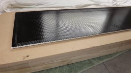
Well guys - I have the first panel running - and just came back from a great audio mates house with proper test gear and pretty dead room . - flat as a pancake in mid / high . Just one nasty 80hz spike that you can detect even without it playing . - I knew it was below 100 , but just what it was and how much of it was seen on the graph . - This sunday , it will be the 2nd panel built with less tension ..perhaps a lot less tension . I only have 75:1 ratio at present too - a decent amp of 150w was used and superb sound was created - just boomy in the 80 hz region . - 3mm thick foam tape stator spacing with 3m VHB tape , 6micron dupont mylar , 260 w x 1200 h driven surface m with a single vertical 3mm foam strip ( 10mm ) up the middle . stators are mild steel with 40% open area . HT inverter & EHT multiplier from ER Audio . Really looking forward to having a second panel built to experience a great sound stage .
Thanks for the inputs above Gerald - I dont have gear to check THD etc .. but friend has just sold some magneplanars and also has a set of appogee stages ? .. big and wickedly heavy - anyway , he has a good ear. - the high diapragm resistance ....- what i noticed was that I can get it to charge in about 10 seconds , if you take the supply away , it will run for ages ..i mean minutes with a decaying energy of course. - but really suprising how long it will hold the charge for. I get flashover from the charge ring to the stator when I drive the EHT to high ,,,its jumping out from the inside around to the outer .- I will shoft it further inside this time round , as i have it near the edge - silly first time mistake . it is prob only about 4mm away via air gap to the stators . Only got 75:1 at present - need another transformer to make a set of 4 to create 150 :1 . - I can see the validity in getting decent transformer now with more ideal windings setup , 4 transformers seems a bit dirty..but the mic test will soon see where im at . - really wishing I hadnt left my scope in Suva - Fiji now !
Hmmm - how to measure paint thickness ? - im just giving them a few coats of Black Epoxy Gloss Enamel . Another weekend gone and still watching the paint dry . - 16hrs minimum before next coat .
Im a bit unsure just how much to tension the mylar - 1.0 % or 1.5% ..or somewhere inbetween . - i understand the physics of going the light tension for resonance being lowered - but there must be much better performance for higher tension , as in quality of the bass . - we all know what wooly uncontrolled woffle sounds like. So im siding with the higher side for now - in the end , it will be like a baby - built with best intentions & breeding stock , but will be what it is once it pops out .
low tension can cause collapsing of menbrame. but on the other hand resonance dictates the lowest frequency it can deliver. so to high means thats the lowest it can get.
btw small note the teroids are not intend to play complete fullrange down to 40 hz. they will saturate as far as i know.
you can spread resonances to use the peak it created and smear it out to gain low end extension. but this is pretty hard and if this is your first build, better to keep it simple i guess.
a fullrange is not an easy task to for a first build. in my opinion go small first or go hybrid first. its more forgiven about allot of things, like the trannies, and as wel with the coating. it beats me but ive seen allot of hyrbids playing with bare metal getting pretty loud without any arcing. but ofcourse there is a thing as safety as well. dont want to kill any one touching the stators...
Congratulations and getting your First panel made and running!!
Be prepared to be in Awe once you get the second one hooked up!!!
Arcing from the edges of metal sators is typically common and due to the sharp edges.
The edges need to be ground down and rounded prior to painting or coating.
Going heavy with the primer helps to seal and round out the sharper edges as well.
A sharp edge (in my case a sharp end of the wire mesh) was the initial cause for the ultimate demise of my little exprimental panels.
Once the coating had gotten burned and damaged I was never able to seal it and obtain the higest platue of voltages that I was running before the First time they had failed.
See this thread on why you need to use a primer and a lot of it,
Post #84,
http://www.diyaudio.com/forums/plan...tric-coatings-fact-fiction-2.html#post2893839
and Post #90,
http://www.diyaudio.com/forums/plan...tric-coatings-fact-fiction-2.html#post2902754
The whole thread is loaded with great info but that is the main section too read on tests I have done using common paints.
More here.
http://www.diyaudio.com/forums/planars-exotics/261177-stator-coating.html#post4039241
Yes you can get good resluts out of a bare metel stator, but once it arcs you start getting holes and a burned diaphragm if you like to push them a bit.
Using a very high resistance stator coating has proven to me that you can push the voltages high enough to cause inoization of the air in the gap without causing any burn holes or damage to the Diaphragm.
This is because there is enough energy to inonize but not enough current inside an arc to burn.
I was running a bias of over >10kv when my panel failed for the last time but it worked even with a .072" D/S.
The eficiency was incredible.
I don't advise running voltages that high on the bias as it was mostly experimental tests that I was doing.
But, You can easily get up to 15KVp-p and more just out of the step up transformer alone.
I was running about 6.5Kv or so and as high 25Kv p-p across the stator's the First time that little panel exploded on me, all becuase of one little sharp point on one of the stators.
I can never ever stress enough how important it is to have an adequate amount of stator coating thickness to assure a long lasting and reliable build!!
Especially when you are using VHB to assemble them, that stuff doesn't come apart eaily in order to do any repairs, even if it is possible at all.
Welcome to the world of ESL Building!!!
Keep Going , I promise you, You won't be sorry for doing it!!
Cheers!!!

jer
Be prepared to be in Awe once you get the second one hooked up!!!
Arcing from the edges of metal sators is typically common and due to the sharp edges.
The edges need to be ground down and rounded prior to painting or coating.
Going heavy with the primer helps to seal and round out the sharper edges as well.
A sharp edge (in my case a sharp end of the wire mesh) was the initial cause for the ultimate demise of my little exprimental panels.
Once the coating had gotten burned and damaged I was never able to seal it and obtain the higest platue of voltages that I was running before the First time they had failed.
See this thread on why you need to use a primer and a lot of it,
Post #84,
http://www.diyaudio.com/forums/plan...tric-coatings-fact-fiction-2.html#post2893839
and Post #90,
http://www.diyaudio.com/forums/plan...tric-coatings-fact-fiction-2.html#post2902754
The whole thread is loaded with great info but that is the main section too read on tests I have done using common paints.
More here.
http://www.diyaudio.com/forums/planars-exotics/261177-stator-coating.html#post4039241
Yes you can get good resluts out of a bare metel stator, but once it arcs you start getting holes and a burned diaphragm if you like to push them a bit.
Using a very high resistance stator coating has proven to me that you can push the voltages high enough to cause inoization of the air in the gap without causing any burn holes or damage to the Diaphragm.
This is because there is enough energy to inonize but not enough current inside an arc to burn.
I was running a bias of over >10kv when my panel failed for the last time but it worked even with a .072" D/S.
The eficiency was incredible.
I don't advise running voltages that high on the bias as it was mostly experimental tests that I was doing.
But, You can easily get up to 15KVp-p and more just out of the step up transformer alone.
I was running about 6.5Kv or so and as high 25Kv p-p across the stator's the First time that little panel exploded on me, all becuase of one little sharp point on one of the stators.
I can never ever stress enough how important it is to have an adequate amount of stator coating thickness to assure a long lasting and reliable build!!
Especially when you are using VHB to assemble them, that stuff doesn't come apart eaily in order to do any repairs, even if it is possible at all.
Welcome to the world of ESL Building!!!
Keep Going , I promise you, You won't be sorry for doing it!!
Cheers!!!
jer
Last edited:
80hz and learning the only way - do it first hand .
Hi Jerald- well , yes , I nod my head regarding the VHB ..very high bond indeed .. Hopefully I will get it apart with a craft knife / stanley knife blade ,... down the middle , so i can recover the stators without bending them . ( hell i hope so ) .
As for HT ..maybe i didnt decribe the arc over quite right ,,, I dont have stator to stator flash over , I have charge ring to stator arcs ... and i know why - the charge ring was placed way to close .about 1mm from the inner edge ..so it was out of sight ..but of course i missed a more important issue - air gap is very close . 3-4mm tops as im right on the edge of the foam . next build I know by inverting the copper and moving it further inside , i can maintain maximum adhesion , but also extend the distance between the charge ring and the stators . ( bearing in mind , if I crank the bias up next time ..the closest distance may well be direct through the VHB foam itself !! ) - this is worse , as it will likely leave a carbonised track mark and make it even easier to strike over here for ever on !! - so its a case of being not too cocky with the bias HT . 80 hz is my demon at present - it showed on a 5mm / 1 meter test analysis in a dead room . shes pretty dead 30 - 80 , 90 - 300 if i recall ... above its totally flat . - so I think once I get the proper drive transformer ratio sorted , 1:150 instead of 1:75 like i have now , things hopefully will improve . tension on the mylar I am sure , I have too tight . - then again , am i about to counter act my changes .. - perhaps the mid bass is low because I dont have the drive , and the 80 hz spike will not be so severe when the other freqs are lifted in comparison . Has to be done to learn though , so I will lower the tension anyhow . - need air comp at home with low pressure regulator and guage - as I was using a simple mark on the film edges as a stretch ref before . its not going to be adequate when trying to duplicate two panels the same tension . - might have to do the suspended weight trick yet - thats a guaranteed method of identical stretch.
yeah i was wondering if the gauge will work. since you have to keep in mind that the inner tube on its own is giving some resistance as well. (at least i think you use the tire method ?) you could also damp the 80 hz, or do you want to get lower? the antec or any other 6 volt power trannie will have difficulties at such low frequency's at higher volumes.
you could take a look at the thread My take on a stretch jig, if you want to use a mic to get the specific frequency you are looking for.
in theory there would be a given pressure to stretch it to a certain frequency. but this as well depends on witch thickness of foil as well of witch kind of foil. and witch kind of inner tube used.
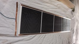
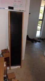
2nd panel built - alot less tension
Just how much tension I have i am unsure . But one thing is for sure - the bass content has rising significantly and dropped to a much lower freq . The 80hz spike has i am quite sure gone all together . - this time I think it sits below 50 - but I have to wait until the measuring can be done . - A diff approach this time , horizontal spars were used at slightly diff distances , keeping the spacing inside the max distance or the width used , I ended up with 250mm square on the first / bottom of the panel , then decreasing with 20mm less each section upwards leaving me with 4 spars and a height of 1210 x 260 wide , 3mm thick . er-audio EHT & inverter kit running on 5vdc , with 4 x (230/6vac) toroids to give me 1:153 ratio stator drive. a totally diff panel to the first build. well worth the effort. enough materials left to build 2 more ... but im out of transformers sadly , so cant even drive two panels at once yet ..what a tease .
Just how much tension I have i am unsure . But one thing is for sure - the bass content has rising significantly and dropped to a much lower freq . The 80hz spike has i am quite sure gone all together . - this time I think it sits below 50 - but I have to wait until the measuring can be done . - A diff approach this time , horizontal spars were used at slightly diff distances , keeping the spacing inside the max distance or the width used , I ended up with 250mm square on the first / bottom of the panel , then decreasing with 20mm less each section upwards leaving me with 4 spars and a height of 1210 x 260 wide , 3mm thick . er-audio EHT & inverter kit running on 5vdc , with 4 x (230/6vac) toroids to give me 1:153 ratio stator drive. a totally diff panel to the first build. well worth the effort. enough materials left to build 2 more ... but im out of transformers sadly , so cant even drive two panels at once yet ..what a tease .
transformer now is my biggest issue
I think now , the biggest issue I have is transformer qualities.
I am working with 4 x RS Comp 671-8959 ( 50VA 2x6v / 230 ) .... I have 1:150 ratio connecting to 0.78nF load .
Looking at my vintage tube amp with an impure thought ! ..will you be my donor ? - Japanese iron from 7189A Pentode P/P Pioneer SM83 .
AT61230 transformers .....
http://www.diyaudio.com/forums/tubes-valves/26431-pioneer-output-transformers-60s.html
I have one of these beside me - really dont want to pull her apart ... https://www.youtube.com/watch?v=um0jO8UsQ00
Last edited:
dont pull it!!!! its a shame. i dont know where you live , but you could get you some transformers from over here.
you need 4 in total
Audiostatic 1:75 40 euro a piece
Quad (63) 1:125 30 euro a piece (cheap why ?? i dont know)
thats 60-80 euro for either 1:150 or 1:250!!!
But especially for the 1:250 segmentation is a must!
Te koop elektrostaten
its in dutch, and im not sure if he ships to wherever you live but, i know the guy that sells them, maybe i can fix something
its a shame. i dont know where you live , but you could get you some transformers from over here.you need 4 in total
Audiostatic 1:75 40 euro a piece
Quad (63) 1:125 30 euro a piece (cheap why ?? i dont know)
thats 60-80 euro for either 1:150 or 1:250!!!
But especially for the 1:250 segmentation is a must!
Te koop elektrostaten
its in dutch, and im not sure if he ships to wherever you live but, i know the guy that sells them, maybe i can fix something
Decon 5 to Defcon 3
Ok - I call it off for now ... but I do need to try proper iron instead of the toroid x 4 collective , its saturating in the bass im pretty sure of that .
To be able to couple a true tube amp transformer from a Push Pull in reverse will allow me to also try the electrostatic panels on my DIY Atma-sphere M60 MKII's . http://i128.photobucket.com/albums/p174/satelliteman_2006/OTL/APair.jpg
These I built many years ago - they still like new .
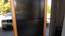
Hardwood broom handles for side support
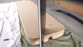
Sunday progress - learnt a few things about routing without proper Jigs ! - tool climbs into the work / or away from it which ever way you view it . - next set the stator wiring will be hiddne inside the wooden supports with a cover strip inserted in the routed slot . - now , just to built the base support / transformer enclosure . - need some nice rimu for that ( NZ native pine )
Sunday progress - learnt a few things about routing without proper Jigs ! - tool climbs into the work / or away from it which ever way you view it . - next set the stator wiring will be hiddne inside the wooden supports with a cover strip inserted in the routed slot . - now , just to built the base support / transformer enclosure . - need some nice rimu for that ( NZ native pine )
Attachments
- Status
- This old topic is closed. If you want to reopen this topic, contact a moderator using the "Report Post" button.
- Home
- Loudspeakers
- Planars & Exotics
- First ESL build - Full Range .