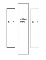
Yes, good luck with glueing the magnets!Now I'm nearing gluing of magnets... For a ribbon, is it correct that N faces opposite S in the gap - as the picture below? Just to be really sure")
regards,
Gerrit
Hi
I have 5micron alu foil made for capacitors. Width is 25mm. Length is unlimited.
Would you part from a couple of meters for some monetary compensation?
//
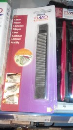
Went to the paper store today and found tgis hope it helps somehow because tge ribbons need some streching tension to work riht, not? It is a metal flange made in the shape of a ribbon of a tweeter as you look at it. I think it might be good for pressing the foil in what good of a performance rate I don't know!
Attachments
Last edited:
According to the spec sheet they use a sandwich ribbon, probably as an alternative to corrugation. The average gap flux is 0.4 Telsa (sic) average, it would be interesting to see a graph of the flux density across the gap.
The more uneven the flux density across the gap, the more corrugation is required to prevent flexing of the ribbon.
Here's a picture of a flat ribbon where the flexing is clearly visible:
View attachment 503623
This is what corrugation is supposed to prevent.
regards,
Gerrit
Did you ever try to apply DC to check the behavior in slow motion/stedy state?
//
Did you ever try to apply DC to check the behavior in slow motion/stedy state?
//
yeah with a very small current would be good idea
Hi,Gerrit, you had a specific setting in DLCP setting (assy shelf?) for compensating the dipole effect - what does it look like - I could not remember where I saw that...
These are the DLCP settings I used for the minimal ribbon test frame:

Using an asymmetric shelf like this is an experiment, the goal was to simultaneously perform the dipole correction and provide the first half of a 24dB/oct LR filter.
regards,
Gerrit
Hi,
These are the DLCP settings I used for the minimal ribbon test frame:
View attachment 518238
Using an asymmetric shelf like this is an experiment, the goal was to simultaneously perform the dipole correction and provide the first half of a 24dB/oct LR filter.
regards,
Gerrit
Nice, i do have to mention that its more common to lower the rest of the freq instead of boosting the lower end, since you run into clipping more early then you would like. just my 2 cents. although its rather high frequency already
you might get away with it more easily. i always got the looks when i did this in an Eq during post production and they are right.Nice, i do have to mention that its more common to lower the rest of the freq instead of boosting the lower end, since you run into clipping more early then you would like. just my 2 cents. although its rather high frequency already
You're correct, but the system will eventually run out of steam somewhere whether it's the DSP or the amps clipping. Remember that I use the analog input so 0dBFS in the DSP is very, very loud. When the digital input is used and the volume is controlled in or after the DSP then only attenuation should be used.
regards,
Gerrit
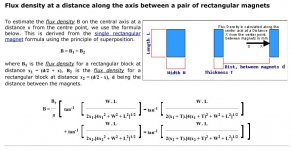
I've put together a small program based on the "Simple Ribbon Equations"
found here:
http://www.diyaudio.com/forums/planars-exotics/50162-another-diy-ribbon-thread-55.html
I've tested it thoroughly, seems to give results coherent with reality.
Happy New Year!
found here:
http://www.diyaudio.com/forums/planars-exotics/50162-another-diy-ribbon-thread-55.html
I've tested it thoroughly, seems to give results coherent with reality.
Happy New Year!
Attachments
Thank you! I will try it as soon as I have a Windows machine available to test it.I've put together a small program based on the "Simple Ribbon Equations"
found here:
http://www.diyaudio.com/forums/planars-exotics/50162-another-diy-ribbon-thread-55.html
I've tested it thoroughly, seems to give results coherent with reality.
Happy New Year!
Happy new year to you too.
regards,
Gerrit
Regarding my program; If you put the mouse pointer on the blue spin edit bars, you can change the values faster....
And the magnet flux calcula uses the enclosed formula.
i have a hard time finding out witch setting is witch. but overal very nice !, wish i could program that well
i have a hard time finding out witch setting is witch. but overal very nice !, wish i could program that well
Ask me if there is any difficulties.
It's the best way to explain the program. And easiest.
- Home
- Loudspeakers
- Planars & Exotics
- DIY ribbon dipole tweeter, reductio ad minimum