Please, if you would, help me determine what to do about my “step up” transformer problem. My goal is to end up with a frequency response of 320Hz to 21,000Hz (+/- 3db) on my Martin Logan panels (I have the bass already figured out so I only seek help with the panel).
I’m getting a sharp roll off above 8,000Hz such that it is about 36 db down at 16,000Hz. And 20,000Hz is nonexistent. It’s pretty flat all the up to 8,000Hz, then boom, it drops off. I would just like to see if there’s a way to configure the step-up transformers to give me a little more highs above 8,000Hz.
** Amplifier: I have 260 watts per channel (two channel stereo only) as follows; A solid state 200W per channel to the bass drivers below 320Hz plus a tube amp at 60W per channel to the electrostatic panels.
** Panels: The electrostatic panels are Martin Logan Monolith III built new by ML about 10 years ago as replacements.
** Transformers: I have step-up transformers that are EI type with a 1:50 ratio (one per panel). They weigh about 2.5 pounds is my ROUGH guess. They are used in the speakers of Roger Sanders. The voltage to the diaphragm is set at 3,500 VDC with the option to go up to 4,000 VDC. The wiring is as simple as you can imagine meaning that there are no passive x-overs thus the step-up transformer is directly wired from the tube amp to the stators using the 8 Ohm taps from the amp.
I realize that I might not ever get a flat response all the way up to 20,000 due to the curve of the panel and all the other reasons mentioned below ;-) . However, I think I’d be happy if the drop was less than 36 db at 16,000Hz…like maybe I’d be happy being down 24db or 18dB at 16KHz, FOR EXAMPLE.
Sank Jew Betty Much,
Eddie
Hi, A couple of thoughts. First are you sure you are actually measuring the response accurately. Even with a calibrated mic and PC set up I get cruddy readings on my MLs above about 12K. The room, mic distance, signal source and measuring technique all work against accurate readings in the HF range. Now is you do have good readings there are some considerations. First the panels act as large capacitors and decrease in impedance as the frequency increases. To get a more linear output you will need to address that issue. I would suspect (ask some of the planar experts on the forum) that you will need to feed the step up with a non linear signal to obtain the performance you want. If you look at the stuff ML uses to get the response (schematics elsewhere on the site) it will boggle your mind. Clearly not an easy task. Good luck with the project.
Hi,
the Monolith´s Panels are some of the larger panels from ML.
Their capacitance as such is high, around 2nF.
Now the stray inductance of the transformer forms a second order lowpass in conjunction with the panel capacitance.
EI-Transformers typically show high values of stray capacitance if not carefully wound with interleaved winding sections.
Those trannies may only reach sufficiently high bandwidth if the panel is of low capacitance, which means it must either be small sized, or electrically segmented (which R.Sanders Panels are).
MLs Sequel used such a simple tranny with a panel of 1nF capacitance and dropped off sharply above 12kHz.
With Your bigger panel 8kHz could well be a perfectly reasonable measurement value.
No electronic equalizing will really help (ML did that with the Sequel and it costed around 15dB in efficiency. But this was only possible in that they used a inefficient partnering bass)
What You simply need is a decent audio transformer with low stray inductance.
I could suggest two options:
1) The toroidal audio transformer designed by Menno v.d.Veen.
They are manufactured by Plitron, Canada and Amplimo, Netherlands
Look for the Model Plitron pat4133-ES or Amplimo VDV-ST105
The are quite costly though.
2) Considerably cheaper will be a pair of toroidal power transformers with their lowvoltage sides connected in parallel and the highvoltage sides connected in series.
120VA-cores will suffice (down to ~100-150Hz).
Best are single-primary-single-secondary types of 230/9V.
115/4.5V will probabely also do, but I have not tested such a setup.
The 230V/9V types are good for 20kHz or higher bandwidth.
See BSAB
for standard toroids (C-RKT-UL120/230/9 for example).
BSAB used to sell the Amplimo/Plitron audio trannies in Germany.
They are specced for min. 4kVrms between primary and secondary.
They are more robust and safe than the specialized audio-trannies, nearly indestructable in this application.
Due to the very lowloss nature of the toroidal transformers issues may occur with certain amplifiers.
The transformer presents the amplifier more of the capacitive nature of an ESL, meaning the phase shift the amlifier has to deal with may reach values of >80° in a range around 4-5kHz and a impedance value of 1R or lower around 20kHz.
The latter is typically not the most critical part, as a a small series resistor between amp and tranny is often required to tailor the amplitude response and shifting the impedance to safer values.
Its the large phaseshift that drives many amps nuts.
So watch Your amp -at lower leveles already- for unusal heating up or sonic irregulars, like harsch metallic sound.
EI-transformers are much lossier and present the amp a much easier to drive load at the expense of sound quality.
Due to the vastly superior sound quality of ESLs they sound handcuffed this way still better than dynamic drivers.
A lucky coincidence as it allowed the manufacturers to build with cheapest crappy transformers, but market those as the superduper specialized and most precious parts You could possibly buy, and allowing many more amplifiers on the market to be used with the ESLs.
As You use a tube amp to drive the panels, the low resistance series resistor mentione above may not be required, due to the copper resistance of the Tube´s output transformer.
My larger panel is of similar size and capacitance as the Monolith´s.
Driven from the Kronzilla DM with their 0.6Ohm output resistance the external resistance may be very small (<0.47R) or omitted with alltogether, depending on room situation and Your taste reagrding the upper highs.
Tubes also are a better match to ESLs than solidstaters as they show themselves les impressed by low impedance and high phase shift.
jauu
Calvin
Last edited:
Eddie,
Try measuring the response with the solid state amp to see the effect of the ESL load. If the ESL panel has 2nF capacitance, then the reflected impedance to the amp is 4 ohms (not including the transformer winding C) at 8kHz and goes downhill above that. The tube amp may not have low enough output impedance to get the treble response.
The 50:1 transformers will also need a high pass filter in the primary as they will saturate otherwise (the Sanders ESL employs hi-pass filtering since the ESL panel is crossed to a woofer and the transformer does not see the low frequency drive ).
Well... What Calvin said is quite correct.
My take on this is somewhat different.
I see a few ways to investigate and proceed.
First is to get a copy of Peter Walker's Wireless World articles on ESLs and how they work, and how to match them with a transformer. Pretty sure they are online now for download, and you can likely dredge up the exact year and month issue information. It's the 1950s, iirc.
Next, based on what that says, I'd go for a transformer with a different goal in mind, and therefore a different turns ratio. That larger capacitance will look like a lower impedance as freq goes up. In practice this may mean that you are unable to use a single transformer to match wide range full audio band.
Imho, this is *the* problem that ML ran into.
Audiostatic solved it one way (see their patents) although apparently they did not stick with putting out product that actually used the patented method! A better model may be the Acoustat 121 interface. That is more likely to work with the problem you have. It uses two xfmrs, one matched low and one matched high, overlapping several octaves. So, consider this.
The higher freq section can be run all by itself, and so you can experiment with that. That xfmr can be considerably smaller and lighter than one use full range or for bass. Things like a 10-25watt output transformer run in reverse may suffice, assuming the proper turns ratio is available.
The third idea is to use an existing tube amp to drive the ESLs "directly" from the plates. This has been done before, and since the tubes plates are HV, they will work to run the ESLs. Of course you will not get full max SPL, but you can see what happens when there is no xfmr involved to the HF response. I haven't looked at this scheme in a long while, but I expect the output iron needs to be lightly loaded with a dummy load (assuming it is still used).
_-_-
Although the esl transformer of Menno van der Veen has a nice frequency response the impedance is horrible. No tube amplifiers can drive such difficult load and many ss have problems too.
Keep in mind that the output voltage of your amplifier for a low impedance is very low so the secondairy voltage of your transformer is also low.
The documentation of this transformer is excellent so read it carefully before you make the decision to buy them.
Keep in mind that the output voltage of your amplifier for a low impedance is very low so the secondairy voltage of your transformer is also low.
The documentation of this transformer is excellent so read it carefully before you make the decision to buy them.
Hi,
the Monolith´s Panels are some of the larger panels from ML.
Their capacitance as such is high, around 2nF.
Now the stray inductance of the transformer forms a second order lowpass in conjunction with the panel capacitance.
EI-Transformers typically show high values of stray capacitance if not carefully wound with interleaved winding sections.
Those trannies may only reach sufficiently high bandwidth if the panel is of low capacitance, which means it must either be small sized, or electrically segmented (which R.Sanders Panels are).
MLs Sequel used such a simple tranny with a panel of 1nF capacitance and dropped off sharply above 12kHz.
With Your bigger panel 8kHz could well be a perfectly reasonable measurement value.
No electronic equalizing will really help (ML did that with the Sequel and it costed around 15dB in efficiency. But this was only possible in that they used a inefficient partnering bass)
What You simply need is a decent audio transformer with low stray inductance.
I could suggest two options:
1) The toroidal audio transformer designed by Menno v.d.Veen.
They are manufactured by Plitron, Canada and Amplimo, Netherlands
Look for the Model Plitron pat4133-ES or Amplimo VDV-ST105
The are quite costly though.
2) Considerably cheaper will be a pair of toroidal power transformers with their lowvoltage sides connected in parallel and the highvoltage sides connected in series.
120VA-cores will suffice (down to ~100-150Hz).
Best are single-primary-single-secondary types of 230/9V.
115/4.5V will probabely also do, but I have not tested such a setup.
The 230V/9V types are good for 20kHz or higher bandwidth.
See BSAB
for standard toroids (C-RKT-UL120/230/9 for example).
BSAB used to sell the Amplimo/Plitron audio trannies in Germany.
They are specced for min. 4kVrms between primary and secondary.
They are more robust and safe than the specialized audio-trannies, nearly indestructable in this application.
Due to the very lowloss nature of the toroidal transformers issues may occur with certain amplifiers.
The transformer presents the amplifier more of the capacitive nature of an ESL, meaning the phase shift the amlifier has to deal with may reach values of >80° in a range around 4-5kHz and a impedance value of 1R or lower around 20kHz.
The latter is typically not the most critical part, as a a small series resistor between amp and tranny is often required to tailor the amplitude response and shifting the impedance to safer values.
Its the large phaseshift that drives many amps nuts.
So watch Your amp -at lower leveles already- for unusal heating up or sonic irregulars, like harsch metallic sound.
EI-transformers are much lossier and present the amp a much easier to drive load at the expense of sound quality.
Due to the vastly superior sound quality of ESLs they sound handcuffed this way still better than dynamic drivers.
A lucky coincidence as it allowed the manufacturers to build with cheapest crappy transformers, but market those as the superduper specialized and most precious parts You could possibly buy, and allowing many more amplifiers on the market to be used with the ESLs.
As You use a tube amp to drive the panels, the low resistance series resistor mentione above may not be required, due to the copper resistance of the Tube´s output transformer.
My larger panel is of similar size and capacitance as the Monolith´s.
Driven from the Kronzilla DM with their 0.6Ohm output resistance the external resistance may be very small (<0.47R) or omitted with alltogether, depending on room situation and Your taste reagrding the upper highs.
Tubes also are a better match to ESLs than solidstaters as they show themselves les impressed by low impedance and high phase shift.
jauu
Calvin
We just had a similar discussion about this a little while ago in this thread just for reference,
http://www.diyaudio.com/forums/plan...nolith-iii-transformer-specs.html#post3786583
If you are driving them from a small tube amp (~50watts) as the frequency gets higher the the impedance gets lower.
So low in fact that your amplifier can not maintain the same voltage output.
This most likely is the cause of your drop of FR response starting at 8Khz and higher.
I don't know about the transformer you are now using but I have measured a few different Toroid Power Transformers and the all have a pretty flat response that extends past the audio range.
However, as mentioned adding a very large Capacitance from a very large panel can have a different effect on the response as well due to the leakage inductance.
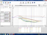
Here are a few measurements I did on a single Antek AN(s)-1206 found here,
A TEST JIG FOR FINDING ESL STEP-UP TRANSFORMER PARAMETERS
The dip you see at 10Khz or so was only there when the HV windings were tied in series.
The transformers that I have been using for the last 4 years don't so this at all.
The peak that you see is the peak of the resonance of the transformer it self as there is no added capacitance in these tests.
If you go to the link you will see some tests were the dip is less prominent and although I had not labeled the pictures with more detail, I believed the tests were done while HV winding's were either left open or connected in parallel as it makes no difference in that configuration.
I never did yet investigate more why the Antek's did this and the ones I use don't.
FWIW
jer")
http://www.diyaudio.com/forums/plan...nolith-iii-transformer-specs.html#post3786583
If you are driving them from a small tube amp (~50watts) as the frequency gets higher the the impedance gets lower.
So low in fact that your amplifier can not maintain the same voltage output.
This most likely is the cause of your drop of FR response starting at 8Khz and higher.
I don't know about the transformer you are now using but I have measured a few different Toroid Power Transformers and the all have a pretty flat response that extends past the audio range.
However, as mentioned adding a very large Capacitance from a very large panel can have a different effect on the response as well due to the leakage inductance.
Here are a few measurements I did on a single Antek AN(s)-1206 found here,
A TEST JIG FOR FINDING ESL STEP-UP TRANSFORMER PARAMETERS
The dip you see at 10Khz or so was only there when the HV windings were tied in series.
The transformers that I have been using for the last 4 years don't so this at all.
The peak that you see is the peak of the resonance of the transformer it self as there is no added capacitance in these tests.
If you go to the link you will see some tests were the dip is less prominent and although I had not labeled the pictures with more detail, I believed the tests were done while HV winding's were either left open or connected in parallel as it makes no difference in that configuration.
I never did yet investigate more why the Antek's did this and the ones I use don't.
FWIW
jer
Attachments
Last edited:
Even if you have a very powerfull SS amplifier there are still problems.
The problem is de serie resistor. No control anymore from your amplifier for the transformer + it makes a voltage divider.
The problem is de serie resistor. No control anymore from your amplifier for the transformer + it makes a voltage divider.
We just had a similar discussion about this a little while ago in this thread just for reference,
http://www.diyaudio.com/forums/plan...nolith-iii-transformer-specs.html#post3786583
If you are driving them from a small tube amp (~50watts) as the frequency gets higher the the impedance gets lower.
So low in fact that your amplifier can not maintain the same voltage output.
This most likely is the cause of your drop of FR response starting at 8Khz and higher.
I don't know about the transformer you are now using but I have measured a few different Toroid Power Transformers and the all have a pretty flat response that extends past the audio range.
However, as mentioned adding a very large Capacitance from a very large panel can have a different effect on the response as well due to the leakage inductance.
Here are a few measurements I did on a single Antek AN(s)-1206 found here,
A TEST JIG FOR FINDING ESL STEP-UP TRANSFORMER PARAMETERS
The dip you see at 10Khz or so was only there when the HV windings were tied in series.
The transformers that I have been using for the last 4 years don't so this at all.
The peak that you see is the peak of the resonance of the transformer it self as there is no added capacitance in these tests.
If you go to the link you will see some tests were the dip is less prominent and although I had not labeled the pictures with more detail, I believed the tests were done while HV winding's were either left open or connected in parallel as it makes no difference in that configuration.
I never did yet investigate more why the Antek's did this and the ones I use don't.
FWIW
jer
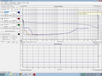
In the Second picture above,
It shows the difference of the Dip not being there in the Paralleled configuration of the HV winding and the response is flat, Sorry for the info box being in the way as I didn't notice this until after I had posted this picture.
The top black line is that of the signal and the next blue line is the response that is blocked by the info box
And the next blue line that has a down slope is the phase of the signal as it is coming directly out of the transformer as measured.
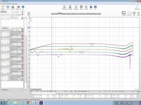
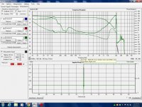
The third picture (as well as 1&4) show the response the the HV winding's in series.
In this configuration it Doubles the ratio and it also Doubles the transformers self capacitance too!!!
This causes 4x whamy on the impedance at the higher frequency's and was probably to much for my Crown DC300A to maintain the same voltage at that level of operation.
The Peak above 10Khz is the Peak that is caused by the transfomer's self capacitance and leakage inductance which was shifted down an octave due to the doubling of the capacitance of the winding's being connected in series.
If I had added any significant amount of added capacitance this effect would be even worse!!!
This is the main reason as to why I suggest to use 4 cores instead of using two cores to get the needed step up ratio.
You get better performance out of your amplifier for the most part.
By using 4 cores you get the same step up ratio but you also get an extended higher range becuase the resonance stays the same as that of a single core (I Think, although I do need to retest this to be 100% sure) and your overall impedance is higher as well before the added capacitance of the panel.
By doing it this way this keeps your peak much higher and gives you more room to work with when you are using larger panels that have much more capacitance.
The lower frequency's impedance's are higher as well due to the Primary's being in series and this also lower's your core's overall saturation point for a given voltage as well.
As the Secondary winding's on each of the core's are now in parallel with each other, this cuts the stray transformer capacitance in half compared to that of the series connected configuration with a single core, thus raising the impedance at the higher end as well before (and after of course) adding the panel capacitance.
FWIW
jer
It shows the difference of the Dip not being there in the Paralleled configuration of the HV winding and the response is flat, Sorry for the info box being in the way as I didn't notice this until after I had posted this picture.
The top black line is that of the signal and the next blue line is the response that is blocked by the info box
And the next blue line that has a down slope is the phase of the signal as it is coming directly out of the transformer as measured.
The third picture (as well as 1&4) show the response the the HV winding's in series.
In this configuration it Doubles the ratio and it also Doubles the transformers self capacitance too!!!
This causes 4x whamy on the impedance at the higher frequency's and was probably to much for my Crown DC300A to maintain the same voltage at that level of operation.
The Peak above 10Khz is the Peak that is caused by the transfomer's self capacitance and leakage inductance which was shifted down an octave due to the doubling of the capacitance of the winding's being connected in series.
If I had added any significant amount of added capacitance this effect would be even worse!!!
This is the main reason as to why I suggest to use 4 cores instead of using two cores to get the needed step up ratio.
You get better performance out of your amplifier for the most part.
By using 4 cores you get the same step up ratio but you also get an extended higher range becuase the resonance stays the same as that of a single core (I Think, although I do need to retest this to be 100% sure) and your overall impedance is higher as well before the added capacitance of the panel.
By doing it this way this keeps your peak much higher and gives you more room to work with when you are using larger panels that have much more capacitance.
The lower frequency's impedance's are higher as well due to the Primary's being in series and this also lower's your core's overall saturation point for a given voltage as well.
As the Secondary winding's on each of the core's are now in parallel with each other, this cuts the stray transformer capacitance in half compared to that of the series connected configuration with a single core, thus raising the impedance at the higher end as well before (and after of course) adding the panel capacitance.
FWIW
jer
- Status
- This old topic is closed. If you want to reopen this topic, contact a moderator using the "Report Post" button.
- Home
- Loudspeakers
- Planars & Exotics
- Step Up Transformer, Need Help Above 8KHz