I did some redesign work on the HV supply; I think I came up with something that will address everyone's concerns:
1. Output is selectable from 700VDC to 7KVDC in 7 steps. Within those steps it is adjustable ~30%.
2. Output is regulated.
3. Music Sensor input or always on with power.
The seven steps are controlled by where R8 is installed (and the associated diodes and caps are poplulated):
Position____RV1 Min____RV1 Max
R8A________700VDC____1000VDC
R8B_______1400VDC____2000VDC
R8C_______2100VDC____3000VDC
R8D_______2800VDC____4000VDC
R8E_______3500VDC____5000VDC
R8F_______4200VDC____6000VDC
R8G_______4900VDC____7000VDC
TP1 can be used to set the output voltage. RV1 will adjust the output at this point between 350-500VDC. The multiplier stages increase this by 2x, 4x, 6x, 8x, 10x, 12x or 14x.
U3 is a LT3751 HV flyback controller and regulates the voltage at TP1. Pin 8 turns the HV section on when high.
Music sensor is essentially the same as before.
Comments?
Attachments
Very Cool!!!
I have only two to major concerns,
First the output of the HV is quite close to the LV circuits and feedback components for 7kv.
7kv can easily jump the rather closes spacing for the resistor pad spacings at the end of the multiplier stage!
Second, the feedback for the regulation section looks okay and would work to keep it quite stable.
But, It won't detect any sudden changes from the actual output voltage coming off of the multiplier stage at any of the later taps.
Or when conditions might change causing a higher leakage rate in the panel that would lower the bias voltage from a normal previous situation of operation, such as humidity changes or other strange phenomena.
You never know when it come to HV.")
I have observed this type of voltage variance and modulations of the Bias voltage in my earlier stages of design before, and is why I chose to monitor the actual output voltage for the feedback control.
I can modulate my supply up to about 100Hz or so, this actually means that it will correct for any fluctuations in the bias voltage up to 100hz.
Above 100hz it is so rock solid that it never fluctuates at all at the higher frequency's.
These are typically filtered out by the feed resistors and circuit capacitance's.
I can increase this 100hz frequency by pulling some of the filtering bypass caps a long the main supply feed to the driver circuit.
As it sits I have no reason to do this.
The reason I was concerned about this is because in my earlier tests (before I added the feedback circuit) I had found that the Bias voltage was being modulated by the driving voltages coming off of the step transformer by as much as 200V to 400V Peak to Peak or more at the lowest frequency's by the driving voltages.
Usually this happened at very high excursion rates when the diaphragm was getting very close to the stator.
This would cause a slight drop in the overall bias voltage as monitored along with some modulation imposed on it as well.
This is can be much as 10% when at a 4kv bias voltage and even worse when operating at a lower bias voltage.
The regulation feedback eliminated a lot of this if not all of it.
I did try it with and without it to prove my theory.
I like your design!!
I like it a lot!!
It is a good start to a very fine supply.
I didn't have any of the LT parts to work with at the time when I started mine.
I wanted to to have a feedback method going directly into the control of the chip, but all I had to work with was the 555 timer that I could get locally should I have burned one out, and it fit the bill quite well.
It was a learning experience for me at the time and knowing what I know now I would have used some of the PWM IC already made for such designs.
I tried to employ the 555 for PWM, But It just wasn't really cut out for that mode very well for the switching range that I needed it to operate in.
When you change the duty cycle of your simple 555 configuration it also drastically changes in frequency.
This compounded issues for the step up transformers Narrow Bandwidth of 175khz to 210Khz or so.
It was hard enough to get a 555 to run this high to begin with.
Luckily I had discovered that I could amplitude modulate the 555 and its frequency stayed stable so that was the method I decided to stick with.
Cost was a big factor for me then and the step up transformer design was still a mystery for me at the time.
It was just a junk box special that turned out better than I had expected.
Yours is a Nice Design, Keep going with it !!!
Cheers !!
jer
I have only two to major concerns,
First the output of the HV is quite close to the LV circuits and feedback components for 7kv.
7kv can easily jump the rather closes spacing for the resistor pad spacings at the end of the multiplier stage!
Second, the feedback for the regulation section looks okay and would work to keep it quite stable.
But, It won't detect any sudden changes from the actual output voltage coming off of the multiplier stage at any of the later taps.
Or when conditions might change causing a higher leakage rate in the panel that would lower the bias voltage from a normal previous situation of operation, such as humidity changes or other strange phenomena.
You never know when it come to HV.
I have observed this type of voltage variance and modulations of the Bias voltage in my earlier stages of design before, and is why I chose to monitor the actual output voltage for the feedback control.
I can modulate my supply up to about 100Hz or so, this actually means that it will correct for any fluctuations in the bias voltage up to 100hz.
Above 100hz it is so rock solid that it never fluctuates at all at the higher frequency's.
These are typically filtered out by the feed resistors and circuit capacitance's.
I can increase this 100hz frequency by pulling some of the filtering bypass caps a long the main supply feed to the driver circuit.
As it sits I have no reason to do this.
The reason I was concerned about this is because in my earlier tests (before I added the feedback circuit) I had found that the Bias voltage was being modulated by the driving voltages coming off of the step transformer by as much as 200V to 400V Peak to Peak or more at the lowest frequency's by the driving voltages.
Usually this happened at very high excursion rates when the diaphragm was getting very close to the stator.
This would cause a slight drop in the overall bias voltage as monitored along with some modulation imposed on it as well.
This is can be much as 10% when at a 4kv bias voltage and even worse when operating at a lower bias voltage.
The regulation feedback eliminated a lot of this if not all of it.
I did try it with and without it to prove my theory.
I like your design!!
I like it a lot!!
It is a good start to a very fine supply.
I didn't have any of the LT parts to work with at the time when I started mine.
I wanted to to have a feedback method going directly into the control of the chip, but all I had to work with was the 555 timer that I could get locally should I have burned one out, and it fit the bill quite well.
It was a learning experience for me at the time and knowing what I know now I would have used some of the PWM IC already made for such designs.
I tried to employ the 555 for PWM, But It just wasn't really cut out for that mode very well for the switching range that I needed it to operate in.
When you change the duty cycle of your simple 555 configuration it also drastically changes in frequency.
This compounded issues for the step up transformers Narrow Bandwidth of 175khz to 210Khz or so.
It was hard enough to get a 555 to run this high to begin with.
Luckily I had discovered that I could amplitude modulate the 555 and its frequency stayed stable so that was the method I decided to stick with.
Cost was a big factor for me then and the step up transformer design was still a mystery for me at the time.
It was just a junk box special that turned out better than I had expected.
Yours is a Nice Design, Keep going with it !!!
Cheers !!
jer
First the output of the HV is quite close to the LV circuits and feedback components for 7kv.
Wasn't sure of the best way to handle that. I used 1812 size resistors, but the user may need to cut and remove the PCB trace between sections connected to the lower voltage outputs. Was trying to keep the project small by not using large thru-hole parts. Also, the voltage multiplier only needs to be populated as far as the highest voltage tap the user wants to utilize.
But, It won't detect any sudden changes from the actual output voltage coming off of the multiplier stage at any of the later taps.
I don't know how you would do this with the LT3751 and the multiple taps on the multiplier and still maintain the same range of adjustment. If you can do a schematic, I can look at plotting it. Most ESLs are hybrids with a Fc of 200-300Hz so they probably don't need regulation at the outputs anyway.
Last edited:
As this is being offered as a DIY project, my bigger concern is whether the user can solder 0603 size components to the PCB. U3 also has a heat sink slug on the underside that needs to be soldered down to the PCB. This would normally require a hot air station to do, but I think I can put a large enough thru-hole centered on the pad that it could be hand soldered from the underside.
The flyback controller is also not a particularly easy circuit to trouble shoot if something is assembled incorrectly.
The flyback controller is also not a particularly easy circuit to trouble shoot if something is assembled incorrectly.
Geraldjr-
Regarding the HV problem; what if the taps were split into two sections as shown on the new plot. Taps 2x, 4x, 6x & 8x would have 3 resistors that add up to 90M (56/22/12 or 47/33/10) and taps 10x, 12x & 14x would be five 18M resistors.
The other possibility is to cover the 1812 resistors and pads with HV corona dope after everything is installed.
Attachments
Last edited:
Unfortunately I am not aware of any SMD resistors that are designed with voltage coefficients in the +1kv range, generally this are only available as through hole parts.
On page 26 the data sheet of the LT3751 it shows that the part is capable of a 1:5 voltage range with just changing the combination of the feedback resistors R10 & R11.
This is a much wider range than 30%.
Although I may be being a bit to technical about this, but In my observations the fluctuations I observed weren't necessarily caused the driving signal itself below 200Hz.
But from the changing dynamics of the signal such as heavy peaks that cause the diaphragm to get very close to the stator or even touching it.
When this happens it can cause the diaphragm to lose some of its charge and at a higher rate.
I believe that this type of modulation can effect the sound quality to a certain extent from being perfect.
If the signal is at a reasonably low level and the bias supply fluctuates just a little bit you can hear this as a change in the output volume even if it is just 10%.
If this change is at a high enough frequency then it is also induced or modulated on top of the sound that is being produced.
On the side of the dynamics when the panel is producing a peak excursion and this peak causes the Bias voltage to drop, due to an increased leakage from being closer to the stator, then this is a form of compression of the peaks.
Therefore reducing the dynamic range that the panel should be able to produce.
If you build the test circuit on page 26 of the data sheet and get it working with 100v to 500v range as they describe, then it is just a matter of adding more stages to the multiplier stack and raising the values of the feedback resistors in the divider accordingly in order to not load down output of the supply.
You can reference my schematic in the link in post 5 of this thread on the proper way of about going about this.
As suggested Flyback design's are a PITA to work with and troubleshoot.
I started with the single FET method and burned up more FETS than what it was worth until I got a design that worked without severely overheating the FET.
This was mostly a gate drive issue of the 555 at high frequency's causing the gate to float and not turn completely off.
Then I switched to the push pull method and got a better efficiency running with cool to the touch FET's.
I don't see why you couldn't just employ the amplitude modulation with feedback technique I used my design using the HV generating circuit you originally purposed.
It is basically the exact same thing, it may save you a big headache in the long run.
I got that idea from a National semiconductor app note.
FWIW
Cheers and Good Luck!
jer
Yes, it is a good idea to coat the board, I just use some 2X spray clear Acrylic.
Splitting the section like you did is a good idea as well and will help if you insist on using SMD resistors.
The ground loop that you have added just makes matters worse inviting a flashover for the highest voltage stages.
As far as the resistors I have never needed to use anything much large than about 30Meg to feed the panels with.
Generally I just used 3 common 10Meg 1/4 watt resistors to feed the diaphragm as found at radio shack.
Typically I only use them if I am feeding more than one panel or both channels with the same supply.
Else it just limits the current through the diodes and saves them from shorting should a flashover occur.
More than this, too large of a value can cause the diaphragm to charge at a lower voltage or a lesser rate due to any leakage paths that may be inherent in the panel.
This has been discussed in several threads and has been proven by many of Tyu's observations on some of his commercial units.
The only thing that can occur should a flash over happen (in the panel or elsewhere) is that it can open the resistor due to their low power rating.
This I have had happen a few times using just 10meg resistors.
For this the voltage coefficient is not of much concern since the current is so low, as long as they don't breakdown and arc over and/or short.
I have had this happen when a ground wire got to close to one of them so extra conformal coating helps with this a lot.
The most major concern of the resistors voltage coefficient rating is in the feedback resistor divider in order to maintain accuracy.
This is why I had to use so many of them since I didn't have any of the special HV resistors that can be quite costly at times.
I explain all of this in the threads.
However using them will save a lot of board space.
I will get my power supply out and do some spark gap length measurements vs voltage for you later on today.
Some of these are already shown in my build thread as well, just to give you an idea.
I had to have at least 100meg to 300meg ( the higher the better) for the total resistance of the divider in order to not load the output voltage too much which can cause it to drop if the supply can't produce enough current.
After the divider there may not be enough current to properly drive the input to the control IC so you may have to employ a high impedance unity gain buffer as I did in my circuit.
Trust me I would not have used another opamp if I had not needed it, so I used the other half for a meter output drive buffer.
jer
It is difficult to layout a PCB from a text description. If someone wants to draw a proper schematic, I'll take a crack at it. I have no interest in providing consulting services of this nature at no charge. I originally offered the design "as is" when I used it in my speakers; the flyback design was borrowed from another project so was fairly straight forward to drop in.
I've seen these group design threads turn into a complete mess, going in 10 different directions at once and people who have no design or mfg experience thinking that products can be created as easily as they are thought up. I'm not going down that road again.
I've seen these group design threads turn into a complete mess, going in 10 different directions at once and people who have no design or mfg experience thinking that products can be created as easily as they are thought up. I'm not going down that road again.
It took me all of two years to design my supply and finally get it into a case and working reliably.
I haven't had a problem with it since I finished it and it has been Three years now.
But I did go through my share of FETs, a couple of diodes and a few 555's by the time I got it too where it is now.
Gotta Love R&D !!!!
jer
I haven't had a problem with it since I finished it and it has been Three years now.
But I did go through my share of FETs, a couple of diodes and a few 555's by the time I got it too where it is now.
Gotta Love R&D !!!!
jer
Last edited:
The ground loop that you have added just makes matters worse inviting a flashover for the highest voltage stages.
The ground plane was always there, I just did the PCB plot without running the ratsnest so it would easier to see.
The dielectric breakdown of air is ~20kV/inch. At 7kV, it should be ~ .35 inches. All of the copper is coated with LPI solder mask which has a very high breakdown voltage. It shouldn't be a problem, but it probably should be prototyped and tried before releasing it to the public.
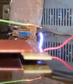
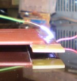
In this post I show the arc length for 4.3dkv.
The ruler I was using is graduated in 1/10".
http://www.diyaudio.com/forums/plan...tor-insulation-mylar-coating.html#post2767803
This one is at aprox. 5.3kv,
http://www.diyaudio.com/forums/plan...tor-insulation-mylar-coating.html#post2767712
Although a bit blurry as I moved the camera but you can see just what a 10.32kv arc can jump,
http://www.diyaudio.com/forums/plan...tor-insulation-mylar-coating.html#post2772703
This all coincides with about 3/8 for 7kv or so.
And at a full 14kv it is approximately 3/4" to just under 1" for a good solid arc.
Before it jumps the gap, if the gap is wide enough, the corona fingers are reaching out and they get longer and longer as the gap is shortened until it finally jumps.
Yes, A good coat of conformal coating will help tremendously with this.
I have found that your typical Clear Acrylic Spray Enamel is good for about 1900v per mil or so.
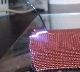
Here are some close ups of this at 14kv, you can tell the distance on my window screen sample as it is common 16/18 holes per inch wire mesh.
jer
The ruler I was using is graduated in 1/10".
http://www.diyaudio.com/forums/plan...tor-insulation-mylar-coating.html#post2767803
This one is at aprox. 5.3kv,
http://www.diyaudio.com/forums/plan...tor-insulation-mylar-coating.html#post2767712
Although a bit blurry as I moved the camera but you can see just what a 10.32kv arc can jump,
http://www.diyaudio.com/forums/plan...tor-insulation-mylar-coating.html#post2772703
This all coincides with about 3/8 for 7kv or so.
And at a full 14kv it is approximately 3/4" to just under 1" for a good solid arc.
Before it jumps the gap, if the gap is wide enough, the corona fingers are reaching out and they get longer and longer as the gap is shortened until it finally jumps.
Yes, A good coat of conformal coating will help tremendously with this.
I have found that your typical Clear Acrylic Spray Enamel is good for about 1900v per mil or so.
Here are some close ups of this at 14kv, you can tell the distance on my window screen sample as it is common 16/18 holes per inch wire mesh.
jer
Attachments
I agree with Pyramid. This will go on forever with modifications and everyone's opinions. Let's just agree on a design without getting too complicated. If we wanted a complicated supply that has tons of features and requires a lot of components and work then we would be better off buying HV supplies in an OEM package. I don't think that anyone wants to spend that kind of money, though.
Yes, 3 or 4 kv is not that hard to deal with and is quite workable.
As I had mentioned earlier at the Very Most 7kv is more than enough for the average system DIY'ed or not and anymore than that you start running in to issues.
As far as over complicating the design, the original design in the very First post is fine, and is nearly the same as my design that has all of the features added except for the remote turn on, and, that is very easily added if one wanted it.
And not to mention a very reliable method to use, Typically no start up problems with such a design.
I preferred to not use the remote turn because of the time it takes for the diaphragm to charge to its fullest potential to begin with, and for it to be on 24/7 takes very little power for it to stay on.
I have had my supply on for months at a time to test this and with the regulation circuit it never ever wandered in the output voltage not even by as much as 10V or 1V or even better.
Now that the design here in this thread has now changed to a PWM type of system, the thing is now starting to get a bit complicated!!
I tried to to implement this when I started as well, and things just got worse as I went along, from driving the FET to getting the transformer to work right with PWM.
However by no means should one give up because it is to complicated to make it work.
It only seems complicated at First when one doesn't understand the process involved when designing a new circuit or way of doing things.
You must keep pushing forward in order to learn new things.
You don't have to add regulation if you don't want too, if the design suits your needs.
I just think that it is beneficial to have it as I have already stated the reasoning's for it.
Adding regulation to the original existing circuit is nothing more than adding a few opamp's and some resistors.
This allowed me to control the output voltage with 1V control voltage input per 1000v of output voltage that is set by a 7V ref IC or any other reference voltage source that you should chose to use.
FWIW
jer
ESL PS0 (First Version)
I'm waiting for parts to prototype the latest design using the flyback controller IC. Not even sure if that is a direction this ought to go, but I'm curious if the design would work better than the original.
In the meantime, to get things moving, attached is the zip file for the original design: what is actually in my speakers currently and working quite well. It puts out ~3.3KV, has limited adjustment and runs from a 12V 400mA wall wart.
I cleaned up the CAD work and schematic to make it a little more readable, and put together an XL spreadsheet (ESL_PSO_BOM.xls) with distributor info and distributor part numbers. The list is not complete; I did not include all the common R's and C's as most people have no problem sourcing these. Just make sure the foot print and voltage ratings are appropriate. The file ESL_PS0_Reference.txt is a complete list of all parts on the schematic with reference numbers, values and foot print.
The other .PDF files are the board layout, parts locator and updated schematic.
The following 7 files are the Gerber X274 files that can be sent to OshPark.com for fabrication:
ESL_PS0.GTL.................Top Copper layer
ESL_PS0.GBL.................Bottom Copper layer
ESL_PS0.GTS................Top solder mask
ESL_PS0.GBS.................Bottom solder mask
ESL_PS0.GTO................Top Silk Screen
ESL_PS0.GKO.................Board Outline
ESL_PS0.XLN.................Drill file Excellon 2.3
The music sense circuit is included, but I found the delay for the panel to charge up to be annoying, so I don't use it. To defeat this capability (HV is supplied any time an external on/off switch is on), install solder jumper on the bottom side of the PCB right below R21. In this case, you do not need to populate any of the parts on the lower half of the schematic. R20 and R21 should be installed regardless. Solder jumper J1 provides a continuous path to ground for these resistors.
This info is provided as is with no guarantees or warranty. The user assumes all risk and liability in assembling this project and in downloading the attached zip file, hereby agrees to and acknowledges these terms and conditions. I have limited time to devote to troubleshooting and support on this; I do not want to get into the business of fixing PCBs for everyone who want to build them, but if you have specific questions about the files, I will do my best to answer them.
The PCB is capable of developing HIGH VOLTAGE in excess of 3000 VDC which may be lethal. Do not attempt this project if you are not skilled in working with electronics and high voltage.
Attachments
I would say 100meg is a good place to start, I used 300meg (30x10meg) in my power supply's feedback circuit.
The complete schematics fir it are at the First link in post #5.
The higher the better as this won't load the source as bad and cause a drop in the voltage should it not be able to supply enough current.
Such as supply's powered with 60Hz and using small capacitors like .001uf to .1uf .
Ohms law will tell you how much loading the resistor divider will be and how much current it will draw.
100Meg at 5Kv is only .250 watts of dissipation.
With only 10meg this would be 2.5 watts!!
For accuracy you want to keep the voltage across each resistor below their rated voltage coefficient.
For 1/4 watt types this is generally about 250V to 350V for the common types, and up to about 500V for some types depending on what brand you use.
I consider 500v fine for a maximum when measuring the varying HV coming out of my step up transformers for testing.
On that jig I only used 20meg ( 20x1meg) worth because that is all that I had on hand at the time.
This worked out withing the criteria of up to 10kv and a worst case Resistor coefficient of 500v and 5 watts of dissipation.
I only use it for up to 5Kv anyhow and was what it was designed for originally.
A step-up transformer driven from an amplifier can keep up with the extra current draw better than that of your typical HV supply.
I have covered this in a few threads showing the math but I forget the key words in order to find them quickly.
I have also found it is best to use a High Impedance input opamp buffer to drive your meter with, at the bottom of the divider as well, for accuracy, and due to loading of the bottom resistor, as it is typically a fairly low value.
jer
I used five 18M smt resistors on the output (90M total) so a 10M meter to ground would form a 10:1 voltage divider. If you read 310VDC on the meter, it corresponds to 3100V. Until the meter makes contact, the full voltage would be available, so it might be best to attache the leads before applying power.
- Status
- This old topic is closed. If you want to reopen this topic, contact a moderator using the "Report Post" button.
- Home
- Loudspeakers
- Planars & Exotics
- ESL High Voltage supply