I thought I'd report on my recent test of the viability of diy screen printing as a technique for creating the pattern of conductors on a planar magnetic diaphragm. I wasn't happy with the results (or work) associated with cutting strips of aluminum so I decided to try etching the pattern instead. High body acrylic paint works great as a resist, and I've found the dried paint can be removed with denatured alcohol and a bit of rubbing. The adhesive I used to attach the aluminum conductors to the mylar substrate seems not to be bothered by denatured alcohol so the next task was to come up with a way to apply the resist (paint) to the aluminum in the desired pattern. For my planar magnetic driver I wanted to make 2 mm wide conductors separated by 0.5 mm so I made a small test pattern to test the resolution of the approach I had in mind.
To do the screen printing I used StencilPro High Resolution pre-coated screen printing sheets and inkjet transparencies, both purchased from Circuit Bridge. The screen printing screens are photosensitive so a conductor pattern can be transferred to them if it is first printed on a transparent substrate.
Here's a quick run-down of the steps I used:
1) Create a conductor pattern as opaque black lines. I drew them in Adobe Illustrator.
2) Print the pattern on a transparency (I purchased transparencies from Circuit Bridge).
3) Lay the transparency on a photosensitive StencilPro sheet, cover it with glass, and expose the sandwich to UV-A light (long wavelength ultraviolet light) for 45 seconds. I used a compact fluorescent black light bulb positioned one foot from the transparency.
4) Develop the screen in water for ten minutes to soften the portions of the photosensitive emulsion that were not illuminated by the UV light.
5) Use water and a soft brush to remove the portions of the emulsion that were not exposed to UV.
6) Fully develop the remaining emulsion by exposing it to UV for at least 10 minutes.
7) The resulting sheet permits resist (paint) to pass through regions that received no UV illumination. The UV-illuminated regions resist the passage of the paint. The screen therefore acts as a stencil to transfer the pattern to a substrate (aluminum foil, in my case).
Results:
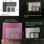
The original pattern is shown in the upper left panel of the image below. The long lines are 2 mm wide, the short lines are 1.5 mm wide. There are gaps of 0.5 mm and 1.0 mm to determine the resolution of the technique.
The bottom left panel shows the pink emulsion on the screen printing sheet after it was exposed through the transparency and then rinsed out. The areas that received no UV illumination appear white. The 200 thread per inch screen fabric not coated with pink emulsion allows paint to be squeezed through during the screen printing process.
I used the test sheet to screen print acrylic paint onto 12 micron thick aluminum foil stuck to adhesive tape (used just for testing purposes). The paint I used was white Liquitex Heavy Body acrylic artist's paint. It is thick enough to retain the pattern without smearing or running, and acts as a very effective resist when etching the aluminum foil. The screen printing result is shown in the bottom right panel. The aluminum appears black in the photo because it is reflecting a dark region of the room.
The upper right panel shows the transparent adhesive tape with the resist and aluminum foil that remained after the unprotected aluminum was etched away by a ferric chloride solution. The photo shows the white paint still coating the aluminum traces because I haven't yet removed the paint with denatured alcohol. I've done that step with other 2 mm wide conductors so I know it works reliably.
I want to make a 220 mm tall by 60 mm wide planar magnetic driver prototype. This test suggests this technique will do the trick. It also looks like the screen printing sheets, once exposed and developed, can be reused enough times so that I can make the many diaphragms I'll need for two planar magnetic line arrays.
Few
To do the screen printing I used StencilPro High Resolution pre-coated screen printing sheets and inkjet transparencies, both purchased from Circuit Bridge. The screen printing screens are photosensitive so a conductor pattern can be transferred to them if it is first printed on a transparent substrate.
Here's a quick run-down of the steps I used:
1) Create a conductor pattern as opaque black lines. I drew them in Adobe Illustrator.
2) Print the pattern on a transparency (I purchased transparencies from Circuit Bridge).
3) Lay the transparency on a photosensitive StencilPro sheet, cover it with glass, and expose the sandwich to UV-A light (long wavelength ultraviolet light) for 45 seconds. I used a compact fluorescent black light bulb positioned one foot from the transparency.
4) Develop the screen in water for ten minutes to soften the portions of the photosensitive emulsion that were not illuminated by the UV light.
5) Use water and a soft brush to remove the portions of the emulsion that were not exposed to UV.
6) Fully develop the remaining emulsion by exposing it to UV for at least 10 minutes.
7) The resulting sheet permits resist (paint) to pass through regions that received no UV illumination. The UV-illuminated regions resist the passage of the paint. The screen therefore acts as a stencil to transfer the pattern to a substrate (aluminum foil, in my case).
Results:
The original pattern is shown in the upper left panel of the image below. The long lines are 2 mm wide, the short lines are 1.5 mm wide. There are gaps of 0.5 mm and 1.0 mm to determine the resolution of the technique.
The bottom left panel shows the pink emulsion on the screen printing sheet after it was exposed through the transparency and then rinsed out. The areas that received no UV illumination appear white. The 200 thread per inch screen fabric not coated with pink emulsion allows paint to be squeezed through during the screen printing process.
I used the test sheet to screen print acrylic paint onto 12 micron thick aluminum foil stuck to adhesive tape (used just for testing purposes). The paint I used was white Liquitex Heavy Body acrylic artist's paint. It is thick enough to retain the pattern without smearing or running, and acts as a very effective resist when etching the aluminum foil. The screen printing result is shown in the bottom right panel. The aluminum appears black in the photo because it is reflecting a dark region of the room.
The upper right panel shows the transparent adhesive tape with the resist and aluminum foil that remained after the unprotected aluminum was etched away by a ferric chloride solution. The photo shows the white paint still coating the aluminum traces because I haven't yet removed the paint with denatured alcohol. I've done that step with other 2 mm wide conductors so I know it works reliably.
I want to make a 220 mm tall by 60 mm wide planar magnetic driver prototype. This test suggests this technique will do the trick. It also looks like the screen printing sheets, once exposed and developed, can be reused enough times so that I can make the many diaphragms I'll need for two planar magnetic line arrays.
Few
Attachments
Last edited:
Thanks guys. The only substrates I've tried are thin mylar left over from an electrostatic speaker project and heavy transparent 3M packaging tape. I used the latter just to simplify gluing the aluminum in place when testing the screen printing. I want to maximize the efficiency and bandwidth of the drivers I'll be prototyping so I want to use the thinnest substrate (diaphragm) that I can make work. When using mylar I glued the 12 micron thick aluminum foil using 3M Super 77 spray adhesive.
I'd consider Kapton as a diaphragm material, which is used by many of the commercial planar magnetic driver manufacturers because it handles high temperatures, but I can't find it readily available in a very thin form. It also tends to be crinkly. I'd really prefer something that is both limp and able to handle the mechanical and thermal stresses. I've never looked into Pyralux. How thin can you get it?
I'd consider Kapton as a diaphragm material, which is used by many of the commercial planar magnetic driver manufacturers because it handles high temperatures, but I can't find it readily available in a very thin form. It also tends to be crinkly. I'd really prefer something that is both limp and able to handle the mechanical and thermal stresses. I've never looked into Pyralux. How thin can you get it?
Last edited:
Great Stuff, Few!!!!
A long while back I had got some samples of Kapton but it I could only get it in 1" and 3" widths.
I thought I had got it from Chemplex but I now don't see it on there list, they have precut pieces but the stuff I got is on a roll.
The stuff I have is 1 mil.
I was also able to get a small roll of some .3mil as well in 3" widths from chemplex.
You can find it by searching up Electron microscopy supplies.
Thin Film Selection Guide - Thin Film Selection Guide - Thin-Film | Chemplex Industries, Inc.
I just found this one for some 6"x100ft tape but it doesn't say what gauge it is, I assume that it is probably 1 mil.
Maybe it is thicker as it does not say.
Order Kapton Tape for 3D Printer Platforms - 6"� x 100' at MediaSupply.com
Uline also has some but again they only stock up to 3" widths and 1mil and 2mil thicknesses,
Kapton Tape, Kapton in Stock - ULINE
I once had a line on some .5 mil stuff I think, but I forget where it was at this time and it was not cheap as you know.
For that I was looking to build something bigger like my Apogee Duette's or along those lines, You know what I mean.")
This was about the best I could find after many deep search's without having to buy a huge roll from Dupont for $5,000 or more.
I have had my samples since 1994 when I first got in to this hobby.
It is out there, But it is not easy to find someone that will supply a small quanity's.
I got lucky with some samples after I had intrigued the sales person with my explanation of use for the product in the design of ESL's and Planer ribbon speakers.
I had got the Kapton for an attempt at some ESL's suitable in the high temp environment of automobiles, But I haven't got that far yet.
Good luck!!!
jer
P.S here is some 1mil x 4"wide,
http://www.kaptontape.com/1_Mil_Kapton_Tapes.php
One more 8"x 8" square sheet,
http://printrbot.com/shop/kapton-tape-squares/
A long while back I had got some samples of Kapton but it I could only get it in 1" and 3" widths.
I thought I had got it from Chemplex but I now don't see it on there list, they have precut pieces but the stuff I got is on a roll.
The stuff I have is 1 mil.
I was also able to get a small roll of some .3mil as well in 3" widths from chemplex.
You can find it by searching up Electron microscopy supplies.
Thin Film Selection Guide - Thin Film Selection Guide - Thin-Film | Chemplex Industries, Inc.
I just found this one for some 6"x100ft tape but it doesn't say what gauge it is, I assume that it is probably 1 mil.
Maybe it is thicker as it does not say.
Order Kapton Tape for 3D Printer Platforms - 6"� x 100' at MediaSupply.com
Uline also has some but again they only stock up to 3" widths and 1mil and 2mil thicknesses,
Kapton Tape, Kapton in Stock - ULINE
I once had a line on some .5 mil stuff I think, but I forget where it was at this time and it was not cheap as you know.
For that I was looking to build something bigger like my Apogee Duette's or along those lines, You know what I mean.
This was about the best I could find after many deep search's without having to buy a huge roll from Dupont for $5,000 or more.
I have had my samples since 1994 when I first got in to this hobby.
It is out there, But it is not easy to find someone that will supply a small quanity's.
I got lucky with some samples after I had intrigued the sales person with my explanation of use for the product in the design of ESL's and Planer ribbon speakers.
I had got the Kapton for an attempt at some ESL's suitable in the high temp environment of automobiles, But I haven't got that far yet.
Good luck!!!
jer
P.S here is some 1mil x 4"wide,
http://www.kaptontape.com/1_Mil_Kapton_Tapes.php
One more 8"x 8" square sheet,
http://printrbot.com/shop/kapton-tape-squares/
Attachments
Last edited:
Mcmaster Carr has 1mil x 6" wide with a 1.5mil sticky backing,
McMaster-Carr
Cheers !!
jer
P.S. this may be where I got the .3mil stuff,
http://www.spexsampleprep.com/equipment-and-accessories/accessory_product.aspx?partnumber=3511
Here is some 24"wide stuff but it is only in 2 mil,
http://www.professionalplastics.com/KAPTONFILMPOLYIMIDE
McMaster-Carr
Cheers !!
jer
P.S. this may be where I got the .3mil stuff,
http://www.spexsampleprep.com/equipment-and-accessories/accessory_product.aspx?partnumber=3511
Here is some 24"wide stuff but it is only in 2 mil,
http://www.professionalplastics.com/KAPTONFILMPOLYIMIDE
Last edited:
Here is some 25"wide by .5mil, Not cheap !!!!
https://shop.eis-inc.com/sap(bD1lbiZjPTAwMQ==)/bc/bsp/sap/zeis2/index.htm?prod_nbr=KAPHN.0005
The whole list of stuff,
http://www.eis-inc.com/suppliers/productlist.asp?prod_area=110&showcase_no=19681
jer
https://shop.eis-inc.com/sap(bD1lbiZjPTAwMQ==)/bc/bsp/sap/zeis2/index.htm?prod_nbr=KAPHN.0005
The whole list of stuff,
http://www.eis-inc.com/suppliers/productlist.asp?prod_area=110&showcase_no=19681
jer
Last edited:
Nicolas: I had to smile when following the link you provided because we had a Tektronix Phaser printer where I work but that was 20 years ago. I don't think it's sitting in a closet anywhere, unfortunately. Interesting idea, though. I guess I'll be continuing with the screen printing for now.
Thanks very much, Jer, for all the kapton information. You dug up more than I was able to. It certainly is hard to find exactly what you'd like in the kapton world. The 8 micron thick stuff looks very interesting; too bad it's not a bit wider than 2 7/8".
I found a patent awhile ago that suggests urethane as a better diaphragm material if the goal is a lower resonance frequency: " Examples of suitable film materials include Urethane, Tefzel® and Teflon® polymer thin films." (Here's a link to Bruce Thigpen's patent.) I think the less crinkly nature of the materials would be advantageous as well. Unfortunately, I've not had great luck looking for readily available thin films (0.5 mil/12 micron or less) of polyurethane.
Hmmmmm.........
I was not aware that polyurethane's were available as a thin film now, what really surprised me was the Polycarbonate can be had in a very very thin film!!!
Ya, the .3 mil Kapton I have is the 2 7/8" stuff and I tried looking but it seems that this is the only width that is available short of buying one of those 2 ton full width rolls from Dupont.
jer
Hi Few,
I do not catch why pyralux LF copper clad wouldn't be a good solution for a membrane.
It is available as a ready to etch (whatever the used etching process) thin flexible sheet (1/2mil copper+1/2 mil adhesive+1/2 kapton)
see http://www.dupont.com/content/dam/a...-materials/assets/PyraluxLFclad_DataSheet.pdf
product refrence LF7012R
Maybe some sample sheets can be obtained from Dupont?
I didn't mean to leave the impression that I think Pyralux is a bad plan. It might be great. My two concerns are that copper is denser than aluminum. It's also a better conductor but the density difference is bigger than the conductivity difference so aluminum is better if you're aiming for minimum mass for a given conductivity.
Also, kapton is probably the best material for small surface area planar magnetic drivers used singly. In that situation heating may be a major issue so the thermal stability of kapton would be a huge advantage. I'm planning to use an array of several drivers so each will be driven less hard. In that context the thermal stability advantages of kapton may be outweighed by the disadvantages of its crinkly nature.
Also, kapton is probably the best material for small surface area planar magnetic drivers used singly. In that situation heating may be a major issue so the thermal stability of kapton would be a huge advantage. I'm planning to use an array of several drivers so each will be driven less hard. In that context the thermal stability advantages of kapton may be outweighed by the disadvantages of its crinkly nature.
I've started using prints as my diaphragm material mounted in a picture frame, so you can pacify the wife if she is a problem. The prints make good diaphragm material, and you can use any picture you want. You don't have the problem with wrinkly diaphragms, or nasty noises of resonance! I was surprised how easy it was and it sounds great. I have a couple of 12" x 16" pictures hanging which sound and look wonderful.
Hi few, there is someone who etched an aluminium foil for building planar headpones :
My DIY Planar Magnetic Headphones and Drivers
Henry, he talks about the epsilon layout ;-)
My DIY Planar Magnetic Headphones and Drivers
Henry, he talks about the epsilon layout ;-)
I just found these folks: GTS Flexible Materials Ltd - Flexible Circuit Laminates - Polyimide Films
They're on the wrong side of the Atlantic for me (perhaps no problem), and may not provide small quantities, but they look good otherwise.
In the meantime I have some very thin aluminized mylar that I may try. The aluminum is too thin to be useful so I'll etch it off and glue on some foil. I just bought it because the mylar is only about 3 microns thick. It feels almost weightless.
Few
Iwouldn't use mylar that thin, I speak from experience, in fact I use mylar or prints about 60 - 90 um. You don't get funny noises like I have with very thin mylar, it only shows up on a few records, but when it does it sounds horrendous.Especially on small speakers, say 60 x 40 mm and smaller. On the larger ones I only goe down to 23 um.
The thinnest stuff I have 1.5um and I have some pure copper leaf that I got from Michael's Art Supply.
I once used it to make the start of a diaphragm on some .3mil mylar but sadly it got discarded by somebody that I had no control over !!!
I had the Gold Leaf Glue to bond the two together and I don't remeber if I had used it or not.
I have been thinking about giving it a try again using the 1.5um stuff I have if I can find the glue.
If I can't find the glue I had what would be a good alternative?
I also recall trying to use rubber cement as well but it has been a long time ago and I don't have any of that at the moment either.
The stuff I have would yield an extremely thin diaphragm providing I can come up with a suitable glue!
jer
Last edited:
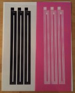
After a couple of hiccups I managed to print a transparency and convert it to a screen printing screen with my new conductor pattern.
The driver will use of 7 columns of magnets, each consisting of 8 NdFeB magnets (1" x 0.25" x 0.125"). The seven columns create six magnet gaps which will be positioned under the six bands of conductors. Each band of conductors consists of four 1.5 mm wide traces spaced 0.5 mm apart. I had to create three separate conductors because my aluminum foil is only 1.5" wide. That's actually fine for me, though, because my goal it to use the separate conductors to control the horizontal directivity of the driver. One column will be used full range (meaning a few hundred Hz to 20kHz), a second will have the highest frequencies filtered out, and the final column will receive only midrange and below.
Each conductor should have a DC resistance of about 2.5 ohms. With four drivers in series I'll get 10 ohms, and then I'll parallel those to get 5 ohms---about where I wanted to end up.
I was very happy to see that the conductors, and just as importantly the gaps between them, made it cleanly onto the screen printing screen. The photo below makes the gaps look less distinct that they actually are because the transparency (on the left) and the screen printing screen (on the right) have minor ripples in them. The ripples cause the shadows cast by the patterns to obscure the patterns a bit. In person things look nice and clear. In use the ripples in the screen will be flattened out when the paint is forced through the screen and onto the aluminum/mylar diaphragm.
Attachments
- Status
- This old topic is closed. If you want to reopen this topic, contact a moderator using the "Report Post" button.
- Home
- Loudspeakers
- Planars & Exotics
- Viability test: DIY screen printing for planar magnetics