hi im trying to design a planar driver, like magnepan , except i want to use a push pull system.
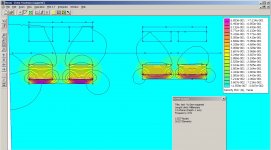
this is what i got so far with magnet rubber band of 5x3mm and the Original 2x6 of magnepan.
the excact strenth is not correct because i really have no clue what the Original strength is. but t gives an idea of dimension and what it does to the gapp. atl least if i understand femm corectly atm.
i only use 2 rows of magnet to see whats going on.
Picture 1
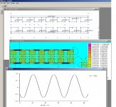
to the left my design to be used with 3-5mm foil instead of wire, and to the right the magnepan design that worked apparantly a little more efficient with wire, something that you can see in femm later on.
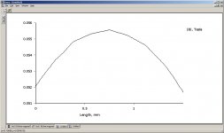
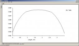
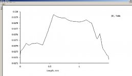
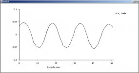
single plot of the magnet strenght ? dont know the name fo it. 2.5 mm above the magnets , is sort of the spacing in a mgnepan, or maybe even 2mm, but for now 2.5 mm will do.
Pic 2
my design , wich looks horible in single ended configuration. the gap is to large and the whole thing colapses.
Pic 3 magnepans design, much better , still rugged, but you can see they have verry limited gaplength where the field is strong, could be reason why foil as the coil,not Always works like wanted.
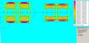
Pic 4 Both designs in push pull.
Pic5 My design in push pull, the with of usable magnet strength has increased allot, when compared to single ended and the magnepan size of magnets.
PIC 6 push pull version of the magnepan magnets.
But the only major problem is , im no expert at this stuff and i can hardly follow FEmm and im already glad i could get this on the screen, but not sure im looking at the right stuff.
So hopefully people that do know something about this matter can assist me a little.
the thing is i want to use foil, sintead of wire. because it allows me to open up more of the metal frame, and its easy to aplly, easy to repair, and without tons of glue allot lighter.
this is what i got so far with magnet rubber band of 5x3mm and the Original 2x6 of magnepan.
the excact strenth is not correct because i really have no clue what the Original strength is. but t gives an idea of dimension and what it does to the gapp. atl least if i understand femm corectly atm.
i only use 2 rows of magnet to see whats going on.
Picture 1
to the left my design to be used with 3-5mm foil instead of wire, and to the right the magnepan design that worked apparantly a little more efficient with wire, something that you can see in femm later on.
single plot of the magnet strenght ? dont know the name fo it. 2.5 mm above the magnets , is sort of the spacing in a mgnepan, or maybe even 2mm, but for now 2.5 mm will do.
Pic 2
my design , wich looks horible in single ended configuration. the gap is to large and the whole thing colapses.
Pic 3 magnepans design, much better , still rugged, but you can see they have verry limited gaplength where the field is strong, could be reason why foil as the coil,not Always works like wanted.
Pic 4 Both designs in push pull.
Pic5 My design in push pull, the with of usable magnet strength has increased allot, when compared to single ended and the magnepan size of magnets.
PIC 6 push pull version of the magnepan magnets.
But the only major problem is , im no expert at this stuff and i can hardly follow FEmm and im already glad i could get this on the screen, but not sure im looking at the right stuff.
So hopefully people that do know something about this matter can assist me a little.
the thing is i want to use foil, sintead of wire. because it allows me to open up more of the metal frame, and its easy to aplly, easy to repair, and without tons of glue allot lighter.
Attachments
Just some of my info........
Magnepan had to put the pole peace in the back MG .5.6 1.6 an 1.7.....when thay went with foil.... Becase it has less output than the wire........i have put the foil from Magnepan thats used on the tweeters of the MG1.6qr on a pr of MG1s ....an i have re-wired with the 36ga wire thay use for tweeters...on more than one pr of Maggys
I well say it close to 3db diff......in output.......the wire for tweerers is ezy to work with but the bass wire is a bitch.....the foil as you are saying will Be ezer to work with but with less output.........may be your dubbel mag....push-pull setup will give more output out of the foil??...........good luck
Last edited:
![URL]](/community/proxy.php?image=http%3A%2F%2F%5BURL%3Dhttp%3A%2F%2Fimg46.imageshack.us%2Fi%2Fdtw9.jpg%2F%5D%5BIMGDEAD%5Dhttp%3A%2F%2Fimg46.imageshack.us%2Fimg46%2F2506%2Fdtw9.jpg%5B%2FIMGDEAD%5D%5B%2FURL%5D&hash=26b6be6a01d4a64c5a7a2d50d5b45e12)
![URL]](/community/proxy.php?image=http%3A%2F%2F%5BURL%3Dhttp%3A%2F%2Fimg547.imageshack.us%2Fi%2Fsequ.jpg%2F%5D%5BIMGDEAD%5Dhttp%3A%2F%2Fimg547.imageshack.us%2Fimg547%2F1925%2Fsequ.jpg%5B%2FIMGDEAD%5D%5B%2FURL%5D&hash=fdcc288b6b283715190d0f913fabda67)
![URL]](/community/proxy.php?image=http%3A%2F%2F%5BURL%3Dhttp%3A%2F%2Fimg51.imageshack.us%2Fi%2Fk5fq.jpg%2F%5D%5BIMGDEAD%5Dhttp%3A%2F%2Fimg51.imageshack.us%2Fimg51%2F4369%2Fk5fq.jpg%5B%2FIMGDEAD%5D%5B%2FURL%5D&hash=b6b9ce7bfc1ad5d1c6b3fc0fc6d830f6)
![URL]](/community/proxy.php?image=http%3A%2F%2F%5BURL%3Dhttp%3A%2F%2Fimg404.imageshack.us%2Fi%2F2y4s.jpg%2F%5D%5BIMGDEAD%5Dhttp%3A%2F%2Fimg404.imageshack.us%2Fimg404%2F7516%2F2y4s.jpg%5B%2FIMGDEAD%5D%5B%2FURL%5D&hash=82aa4ef85f76c2bd2f9e026706dfdd92)
Nice model.
ok i redit it and used the other tangential thingy, to display the field.
bandsei what sizes are ur neos and what is the foil to magnet distance in ur drawing>
i settled now for a push pul with in the drawing ceramic 5 magnets, but this will be the way lower magnetic rubber magnet. the thing is that the single ended magnepans uses this type of magnet. so i drawed the same dimensions of the magnepan version to compare what happens if i make my own version. so strength in the graph is not saying much (in Tesla numbers) only comparing the one magnet structure to the other, for the foil i want a wide gap. this is what i got now .
the flux is not much in my gap copared to that neo design and is gone be even lower, but if you compare it with the Original magnepan design its still almost 2 as strong and over a much wider range, wich helps to use foil instead of a wire.
ooh i so want to start building but first have to tackle the 300 euro investment for 200 meter magnet........ hate 160 euro of shipping costs
oh one thing Bandsei, the foil conducter in ur design is Always blocked or at the front or the back. im not sure if it makes any diference, can you model that version with ceramic 5 ?
ok i redit it and used the other tangential thingy, to display the field.
bandsei what sizes are ur neos and what is the foil to magnet distance in ur drawing>
i settled now for a push pul with in the drawing ceramic 5 magnets, but this will be the way lower magnetic rubber magnet. the thing is that the single ended magnepans uses this type of magnet. so i drawed the same dimensions of the magnepan version to compare what happens if i make my own version. so strength in the graph is not saying much (in Tesla numbers) only comparing the one magnet structure to the other, for the foil i want a wide gap. this is what i got now .
the flux is not much in my gap copared to that neo design and is gone be even lower, but if you compare it with the Original magnepan design its still almost 2 as strong and over a much wider range, wich helps to use foil instead of a wire.
ooh i so want to start building
but first have to tackle the 300 euro investment for 200 meter magnet........ hate 160 euro of shipping costsoh one thing Bandsei, the foil conducter in ur design is Always blocked or at the front or the back. im not sure if it makes any diference, can you model that version with ceramic 5 ?
Attachments
Last edited:
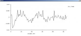
Look at the b.n (normal) and b.t (tangential) fields instead of the /B/.
It could also be useful to use the vector plot (view/vector plot/B).
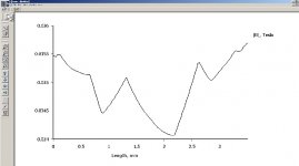
hmm if i do that i get this... why does it looks so rugged, and the not push pull looks nice and clean ?
Here the b.n (normal) pictures, can you tell me what is hapenning
first picture is the push pull, and second is the single ended, wich looks far beter ? any idea
Attachments
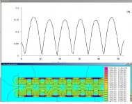
if i let all the arrows of the magnet direction point down i do get a nice graph like the single ended. BUT if i remember correct the magnets have to reppel eachother if you stack an exact same pannel as this behind the first one.
am i going mad or what? now the foil should be directly behind the magnet. instead of in between? the firsl is way stronger now. hmm
am i going mad or what? now the foil should be directly behind the magnet. instead of in between? the firsl is way stronger now. hmm
Attachments
Last edited:
ok i tried in real life , putting the foil in between the magnets like the above picute, result sucks. field may be 2 times as high but it aint working.i stick with the first push pull with back magnets repelling from the front. its increases sensitivity and lowers distortion. but i still would like to know what the
(normal) and b.t (tangential) fields instead of the /B/.
the vector plot (view/vector plot/B).
exactly means
(normal) and b.t (tangential) fields instead of the /B/.
the vector plot (view/vector plot/B).
exactly means
Vector plots (from the manual):
"A good way of getting a feel for the direction and magnitude of the field is with plots of the field
vectors. With this type of plot arrows are plotted such that the direction of the arrow indicates the
direction of the field and the size of the arrow indicates the magnitude of the field. The presence
and appearance of this type of plot can be controlled by pressing the “arrows” icon pictured in Figure 2.19."
Also from the manual:
"/B/ Magnitude of the field intensity along the contour;
B.n Component of field intensity normal to the contour;
B.t Component of field intensity tangential to the contour;"
Plotting /B/ gets you the magnitude regardless of direction/"polarity".
The /B/ plot in of no use when evaluating these circuits.
Using my simmulation in real life the 2 parts will repell each other as yoy try to assemle them.I have just tried with 3 magnets.
Have you read this tread?http://www.diyaudio.com/forums/planars-exotics/242503-b-g-rd-50-dissected.html
Bernt Båndsei
Have you read this tread?http://www.diyaudio.com/forums/planars-exotics/242503-b-g-rd-50-dissected.html
Bernt Båndsei
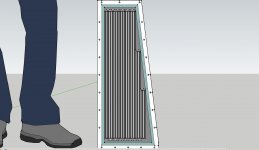
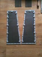
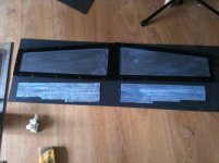
Well got my drawings ready, tommorow i will build a Mini planar , the same way i want to make the biger one. it uses rubber magnet from an old magnepan. and is in push pull config. coil will be 40 micron 3 mm width alumnium foil with adhesive. so no glue crap. and trapezium design to see if it helps spreading the resonance frequency
will cnc the white coloured frame tomorow, the blue portion is 1 mm deep to the metal perforrated plate (that is not drawn yet and bought tomorow) will flush so the magnets get a distance of 2 mm from the mylar, on both sides
the black are the magnets the white/greyish line is the foil.
calculated distancce is around 6.5 meters of foil, resistance will be around 1.5 ohm, so not a number i would prefer but for testing ill ad an resistor, i dont care if it screws up the higher band, becaus thats not his duty.
total square conducting mm2 = 20731,8 mm2
im prety curious how this will translate , instead of using a thin wire.like magnepan
Attachments

That all sounds about right.
But Magnepan does use foil on most of their newer models. My older MG-12/QR speakers had 2.5mm-wide foil for the tweeter section. And I believe that the MG-3.7 and MG-20.x use it for everything. All of the models with the "/QR" suffix use it for their "Quasi Ribbon" tweeter section.
Here is an unofficial list of most of the older Magnepan models, with some of the specs:
http://www.integracoustics.com/MUG/MUG/articles/speakers.html
The only suggestion I can think of would be to possibly have two separate sections, so that bass and mid can be separated from treble. Of course then you need a crossover.
Thx gootee, i know the list verry helpfull indeed. i even think the verry latest models use printed traces. something i could only dream off. i like it way more. no buzzing all looks nice and slik no glue
probable has some drawbacks as well, price , conductivity maybe wieght ?
probable has some drawbacks as well, price , conductivity maybe wieght ?
TIME TO BUILD!!!
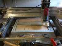
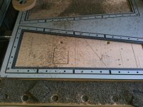
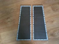
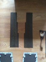
Well i went up early to go to the metal shop nearby, and got the perforrated metal. in the end i chose 2mm instead of 1 , its bit more sturdy, i do think its pretty expensive , 35 euro for 4 panels and a rod of 3mm x 10x500mm
ok made some drawings for toolpaths for the cnc. ofcourse just before i wanted to start my pc chrashed so my Y axes ran in to the end stop. wich means the the motors that drive the X axis along the y are out of alignment good start. reminds me i have to get my end switches fixed.....
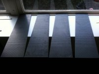
well after some fidling i cnced my to sides, and all the tiny things to clamb the metal. i dont want to use glue so i can change the mylar magnet distance. the tiny pieces are not done to a high standard, because i dont have an vacuum table i either have to leave stock so the parth does not fly away, or screw it down. both means more work so i just let them fly away, wich once in a while leaves some broken off stock on the part.
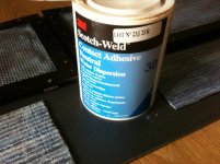
after that i cut the magnets from an old magnepan in size, and put the glue magnepan uses on the mylar on the magnets and the metal plate. now wait for 30 minutes and then the next part will follow
Well i went up early to go to the metal shop nearby, and got the perforrated metal. in the end i chose 2mm instead of 1 , its bit more sturdy, i do think its pretty expensive , 35 euro for 4 panels and a rod of 3mm x 10x500mm
ok made some drawings for toolpaths for the cnc. ofcourse just before i wanted to start my pc chrashed so my Y axes ran in to the end stop. wich means the the motors that drive the X axis along the y are out of alignment
good start. reminds me i have to get my end switches fixed..... well after some fidling i cnced my to sides, and all the tiny things to clamb the metal. i dont want to use glue so i can change the mylar magnet distance. the tiny pieces are not done to a high standard, because i dont have an vacuum table i either have to leave stock so the parth does not fly away, or screw it down. both means more work so i just let them fly away, wich once in a while leaves some broken off stock on the part.
after that i cut the magnets from an old magnepan in size, and put the glue magnepan uses on the mylar on the magnets and the metal plate. now wait for 30 minutes and then the next part will follow
Attachments
- Status
- This old topic is closed. If you want to reopen this topic, contact a moderator using the "Report Post" button.
- Home
- Loudspeakers
- Planars & Exotics
- trying to get around FEMM and a push pull magneplanar