I am in the process of collecting various planar isodynamic speakers.
I am not talking about tweeters...the market is full of them.
I am talking about units able to play midrange or even mid-bass region.
It all started with the planar mid of my speaker (Quadral Vulkan MKV)
and since then i have bought another two same units, an L-EMIM from an
Infinity IRS Epsilon speaker, three Fostex FS21RP and recently (expecting
it within the next days) a Fostex FS41RP.
My aim is to open all and take measurements in an attempt to make something similar of my own or modify them to my needs.
I have studied everything i could find on those speakers and i would like to ask a few questions if someone is able to shed some light...
For instance: i have the Quadral unit in my hands.
The ribbon element must be of kapton (?-yellow) and the aluminium traces are in the back.The exposed to air surface is (7X11) cm.The magnets are neodymium and in the Vulkan MKV is crossed at 400 Hz to the woofer and at 4000Hz to the ribbon tweeter.From what i saw i believe with a third order cross.There is no foamy/hairy agent glued to the back of the magnets to prevent the ribbon from touching the magnets.
Now i take the Fostex FS21RP.Again a mid range isodynamic planar.
The ribbon is again yellow (kapton?), the aluminium traces are in the back,the magnets are samarium cobalt and the exposed surface is much bigger to the Quadral (7X17.5)cm- so about 1/3 longer!
On every other row of magnets there
is a foamy agent glued to prevent it from touching the magnets
However it has a breakup mode at 650Hz which makes it unusable
below 750Hz.
It has a bigger diaphragm and should be able to play lower but it doesn't.
Question:What is the reason for this?
Is it the magnetic gap that is narrower?
Are the protective foams the reason for lesser displacement("excursion")?
Is it due to the magnets or the shape of the planar?
Any thoughts are welcomed...
the determining facts include the maximum excursion possible and the mass of the diaphragm.
keep in mind that a diaphragm held solidly on all sides will move like a jump rope - the most motion in the center at low frequencies. so, a wider diaphragm may need a means to keep the diaphragm from contacting the front or rear magnet rows (if that is how it is made).
The distance to the magnets plays a role as well.
No free lunch is what is said about these things...
_-_-bear
If it's truly a breakup mode and not the fundamental mode there ought to be a node (or nodes) in the diaphragm's motion when driven at 650 Hz. You might be able to find it with a microphone moved very close to the diaphragm. If you can determine where the node(s) is (are) you might be able to figure out a way to damp that mode and make the driver useable to a lower frequency. You might at least get a clue why it's a problem with one driver and not the other.
Few
Few
The hardest thing for a diyer is to make a diaphragm...
I am thinking about a modified unit keeping the same diaphragm.
I even have a source for these.
My first attempt will be to take out the protective foam strip and
see if this allows for a greater excursion.
If the limiting factor is this, then by separating the magnets a bit more
(say a couple mm) i can make it go lower...?
I know that i will be weakening the magnetic field and decreasing the
speakers sensitivity.
But we are talking about a speaker with 90dbs/watt/m so a bit lower
would be acceptable...especially if used in arrays.
If that would prove true than my next step would be to replace the
samarium cobalt magnets by neodymium ones that will be one mm shorter.
Having in mind that S/C magnets have a maximum power of around 30 MGOe (N30) whereas the neodymium ones start at 35 MGOe (N35) and go up to N50+ makes things easy in using smaller magnets and keeping the field intact.
This way i will have no decrease in the magnetic fields and space for a
larger excursion...
Is there a flaw in my logic?
Hello S of V,
Perhaps I'm just misunderstanding your intent (i extend my apologies in advance if I am) but I think you may be confusing low frequency extension and excursion limits. Unless the diaphragm is actually contacting the elements that you say might be limiting excursion those elements shouldn't have a significant impact on the low frequency extension.
It's true that low frequencies require more excursion than high ones if the same output level is to be achieved, but as long as you're not reaching the excursion limits I think your fundamental resonance is largely determined by the tension, mass, and dimensions defined by the clamped edges of the diaphragm.
If your diaphragm does touch the "foamy agent" even at zero or very low excursions then I would expect it to affect the fundamental resonance frequency.
Few
Hi Few, and thanks for your input.
I would expect diaphragm mass to be a restrictive parameter when one is trying to "push" to higher frequencies.
That's why a similar woofer cone is heavier than a mid cone and tweeter dome is lighter
than a mid cone.
And from searching about diaphragm weights i have seen than let's say Infinity uses
progressively heavier diaphragms from Emit to EMIM to LEMIM...which means that weight is something you want when going lower...maybe for dampening vibration modes?
My question lies with the fact that a larger diaphragm with similar characteristics
is 300 Hz "shorter" at the low end...
Even the width is the same...maybe it is a matter of tension.
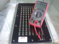
I will know when have opened them and make measurements of the gap and tension.
More measurements to follow...
I would expect diaphragm mass to be a restrictive parameter when one is trying to "push" to higher frequencies.
That's why a similar woofer cone is heavier than a mid cone and tweeter dome is lighter
than a mid cone.
And from searching about diaphragm weights i have seen than let's say Infinity uses
progressively heavier diaphragms from Emit to EMIM to LEMIM...which means that weight is something you want when going lower...maybe for dampening vibration modes?
My question lies with the fact that a larger diaphragm with similar characteristics
is 300 Hz "shorter" at the low end...
Even the width is the same...maybe it is a matter of tension.
I will know when have opened them and make measurements of the gap and tension.
More measurements to follow...
The size, tension, mass, the spacing to the magnets and the magnetic force, all affects the frequency response. If you want to go lower, you will have to sacrify something else. Below the fundemental resonant frequency the output will drop rapidly. Reducing the tension will lower the resonant frequency at the expense of losing headroom. It is also very difficult to lower it without having a peak at the resonance, that will consume the already limited space for large excursion of the diaphragm. In the end it is all a matter of balancing different properties.
SofV, you did not say what your "needs" might be??
So it is hard to figure out what might be a good answer.
Think about this, the people who build these drivers are experienced, have done multiple tests and prototypes and you see what they have offered as products (small and larger sized). Pretty much these are based on the constraints of the technology and physics... so if you want something that does not exist at any price there may very well be a good reason for that.
My needs...I would love to get it around 300Hz with a sensitivity of 85dbs.
I understand you point but these designs were made in the 80-90 era.
I have in hand smaller planars that CAN go lower... way lower.
This proves that the physics boundaries is not the case here.
Materials and production parameters ... maybe.
For example they do not have neo magnets.
This leads to smaller magnet gap (to keep the field uniform) which may be the reason
for limited excursion...
One evil leads to the next.
I will open and report.
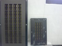
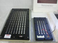
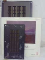
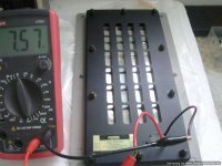
Got them both.
I have to say that the FS41 looks great.
5 kilos weight and the diaphragm tight as a drum some 30 years later!
I haven't seen any L-EMIM looking this tight!
I have to say that the FS41 looks great.
5 kilos weight and the diaphragm tight as a drum some 30 years later!
I haven't seen any L-EMIM looking this tight!
Attachments
- Status
- This old topic is closed. If you want to reopen this topic, contact a moderator using the "Report Post" button.
- Home
- Loudspeakers
- Planars & Exotics
- Why this one goes lower?